Feb 17, 2015

Use Google Drawings to start a 3D Model

If you want to start 3D model from a custom graphic, logo or photo, you'll find that most 3D Modeling apps don't let you import an image to trace. Apps like Autodesk Tinkercad or 123D Designer allow importing of Scalable Vector Graphics (SVG) format files, but most people have not even heard of SVG, let alone know how to generate one from an image they have.

Watch the video (embedded above) for a 3 minute lesson on how to do this - and read on for some details.

Use Google Drawings - or Google Slides - to create SVG

If you create a drawing in Google Drawings or Google Slides, you can export an SVG format of that drawing for use in a 3D Modeling app! While Drawings and Slides don't have all the pro tools some experts might expect in a product like Adobe Illustrator, they are much easier to use and allow for something that I've found to be quite handy - that is, tracing an image to create the beginnings of a 3D Model. Go to Google Drive and click the NEW button (it's a CREATE button if you're still using the old Drive interface) and then select Google Drawing, which might be under "more" if you don't use it often. That will take you to a blank page to start your drawing.

Trace an image to create SVG

To trace an image as the basis for your eventual 3D model - use the INSERT / IMAGE feature to grab the image you want to trace. Of course, you could just draw using the shape and drawing tools, but if that's all you wanted, you may as well have started in your 3D modeling app. Once the image is there on your canvas, scale it to a workable size. Now, use the line tools to trace it. I like the Curve and Polyline tools for this. Just start at any point on the edge of the object you are tracing and click as you form lines until you can create a closed shape around the object. Use ESCape to end or stop if you make mistakes. When you are done tracing, click off the trace and click the underlying image and delete it.

Download as SVG.

In the FILE menu of Google Drawings is the "DOWNLOAD AS..." option. Use that and select "Scalable Vector Graphics (.svg)" option. That will download the file to your machine - usually into the "downloads" directory.
Import the SVG file into your 3D Modeling App
Depending on what 3D modeling app you use, there will be some "IMPORT" or "OPEN" command which will ask you to pick the file to upload. Navigate to the directory which contains the .svg file you saved and import it. From there, you should know how to "extrude" that into an object in your 3D modeling app. I use Autodesk 123D Designer mostly, and this process is extremely easy.

Watch the video in this post to see the whole process.

Feb 15, 2015

Multi-Color 3D Printing Using Snap Together Parts

In my first few weeks with my 3D Printer, I was on a roll making 3D Models & prints of product logos - specifically the Google Apps products that I've been involved with. But, there was one product I was avoiding because of it's multiple color scheme - Google Drive.

The Google Drive logo is an equilateral triangle of 3 colors - blue, yellow and green. But, look at it closely and you'll also notice it is made up of 3 identical parallelograms - rhomboids, actually - as each side of the triangle, which fit together to form that shape.


Given that I had already experimented with snap together shapes, I decided the Google Drive logo was worth a shot.

I was sure that I could design and model just one part and then print it in 3 separate colors, which would then snap together to form the Google Drive logo.

The model was a variation on the experimental snap-together part I had previously designed. This one was would be more mathematically beautiful - with 60 degree (or 120 degree, depending on how you looked at it) angles between the horizontal and vertical parts of the rhomboid. That's what makes the triangle work when three parts are connected (remember that the sum of the 3 internal angles of any triangle equals 180 degrees; so 60 + 60 + 60 in this case)

The single part, printed in blue, green and yellow - with snap-together goodness - formed the Google Drive logo!

As a bonus - I found that these parts could be snapped together in other ways to form cool shapes and sculptures. I expect to do much more with the basic deisgn - but for now, I'm happy to print a few of these for some friends and co-workers who are fans of Google Drive.


Feb 13, 2015

Experimenting with Plastic Joints - Mortise and Tenon

Making interlocking 3D printed objects gives you new super powers when making things. For example:
  • Make models which cannot be printed in a single print due to overhanging sections or other complexities which are difficult in Fused Filament Fabrication (FFF) printing.
  • Make models which have adjustable and moving parts using hinges and rotary joints.
  • Make multi-color models, where different parts can be printed in different colors.
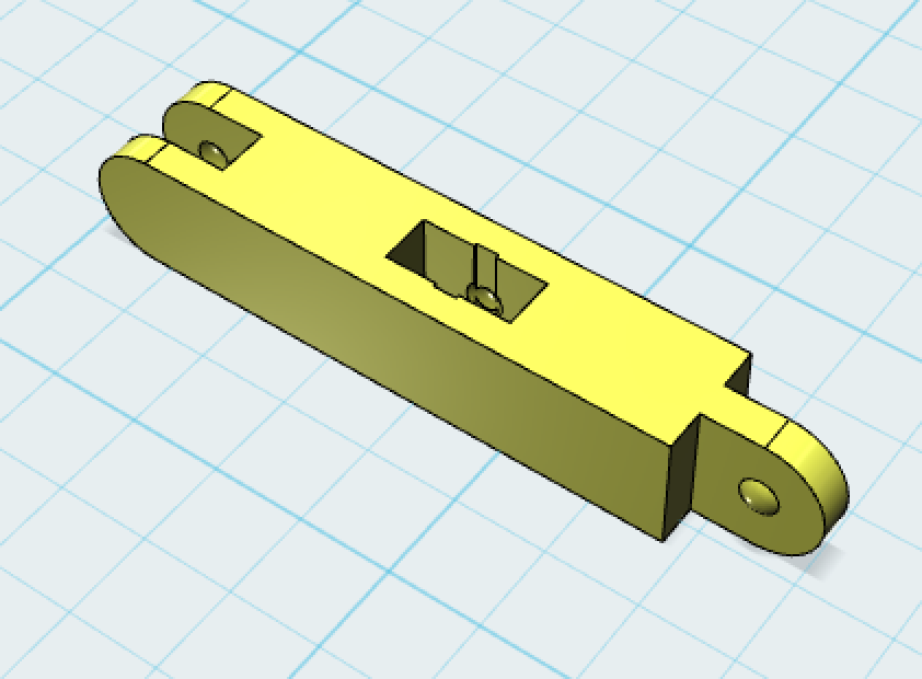
The final object with center mortise and rounded tenon
My first attempt of designing, modeling and printing a simple joint actually went pretty well, after some experimentation, and taught me some basic things about one joint type - a mortise and tenon. 

A mortise-and-tenon joint is basically a fitting where one end - the mortise - is a hole or gap, where the other end fits perfectly to fill that hole or gap - making a tight enough fit to hold. It seemed to me that the best way to get this effect was to use "subtractive" modeling (In Autodesk 123D Design, that is called the "Combine" / "Subtract" command). This means first modeling the tenon, then subtracting that tenon from the 2nd object to make a perfect mortise which fits that tenon.

The tenon in my experiment was going to be just a rectangle stick - and the mortise, therefore, the inverse of that - a rectangle hole the same exact dimensions. 

Making the Tenon

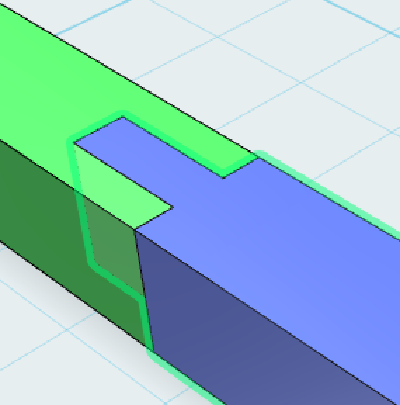
the tenon with locking button
This is fairly simple - I just created the main shape the dimensions I wanted the finished part WITHOUT the tenon. Then I created the tenon shape as a separate rectangle, connected it to the end of the main shape, centered and aligned, and combined the two.
I wanted to add a bit of a "locking" mechanism to this joint I added a very small bulging "button" on either side of the tenon. I made this by simply overlapping a sphere with a diameter slightly larger than the width of the tenon onto the tenon itself, and then combining the sphere with the tenon.

Making the Mortise

using the tenon to create the almost
perfect mortise
Once the tenon was designed, I was ready to subtract it from an object which would become the mortise. I overlap the tenon into the area where I want the mortise, aligning it so there is enough of a wall  around all sides of the mortise area - and sinking it to the proper depth - and then subtract the tenon shape from the mortise shape. Remember, that most subtraction actions completely delete the tenon - so I recommend duplicating the tenon and saving it on the side so you can use it again if necessary.

Now we have a perfectly (too perfectly) fitting tenon and mortise. After that subtraction, the mortise is exactly the dimensions of the tenon which will fit into it - but with zero clearance, which means in real life the tenon will be way too tight to actually fit. I used a simple method of adjusting the tenon and/or mortise to make the parts fit together well. I select the faces of the tenon which will be inside the mortise, and I push them in (toward the center) by approximately 0.4 - 0.5 mm on each side - giving ultimately 0.8 - 1mm of clearance on the horizontal and/or vertical dimension of this joint. I also reduce the bulge/button by that amount if the face reduction didn't do that automatically.

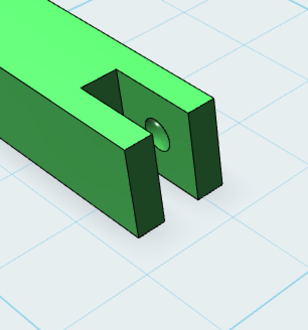
The mortise with inverted
locking button to grab the tenon, after
expanding each side just a bit
Notice also, that I wanted a two-sided part, with a mortise on one side and a tenon on the other, which would give me flexibility to make continuous connections (like a construction toy!). So, I
replicated the main shape which had the tenon on one side and made the mortise on the back side of that using the replicated shape as the subtraction shape.

Dimensions of the Mortise and Tenon

The fit of the resulting joint depends on the quality and precision of the print. That 0.8-1mm of clearance worked well for me on tenons of approx 2mm - 8mm for objects of about 50mm - 100mm long/wide. You'll likely have to experiment to get measurements precise for your needs.

Adjustments & Features

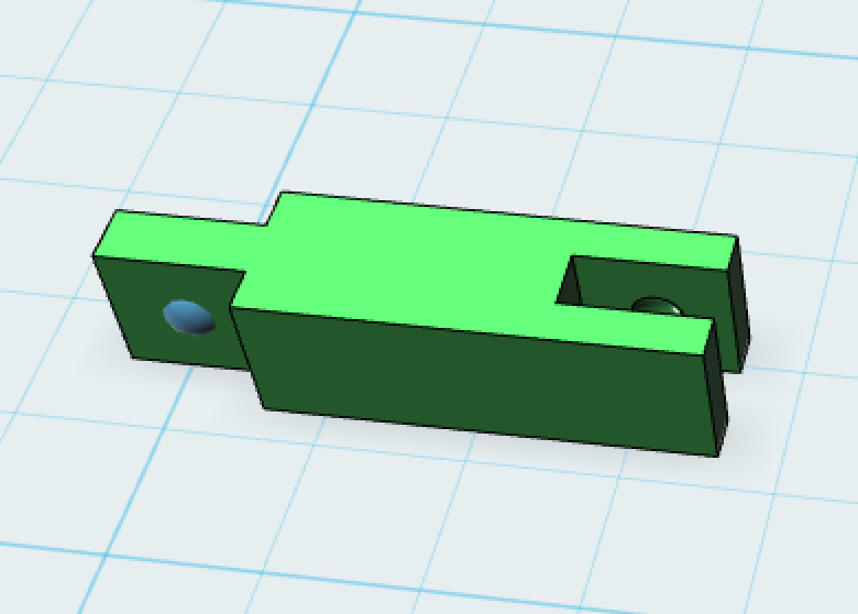
The almost final part,
before rounding the tenon and adding
the second mortise in the center
I ended up wanting my joints to rotate in one dimension - so I rounded the end of my tenons to allow for this. I also made some slight increases in the clearance of the end of the tenon with the shoulders of the mortise so that rotation was not inhibited.

I also wanted to be able to insert parts into the center of other parts, so I added an additional mortise in the middle of each. Notice I had to add a small channel to make it easier for that button on the tenon to slip into the center mortise. 

Some details of the experimental joint

My experimental part was 30mm x 5mm x 5mm - with the mortise/tenon on the 5mm x 5mm end. The tenon ended up being 5mm (covering the total width) by approx 1.66mm (one third of the 5mm width to make each side of the tenon also 1.66mm).

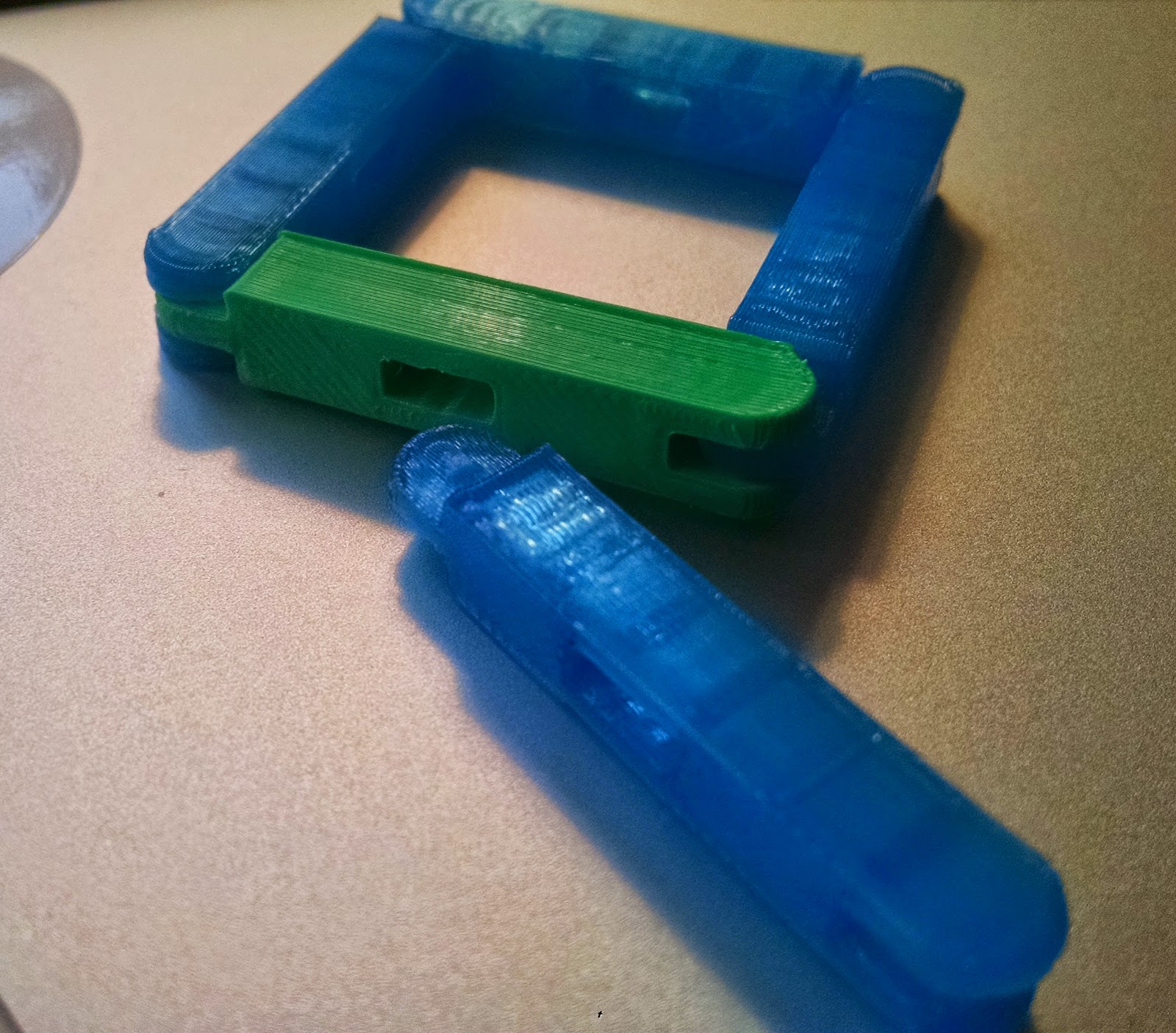
Here are 5 parts, 4 of which are snapped together into a square
Printing these parts was optimized by making sure there were no overhangs or gaps to bridge - so I printed the tenon on it's side so it had support on the bed, and the mortise in the same orientation. All the mortises and tenons were vertical in orientation on the printer bed.
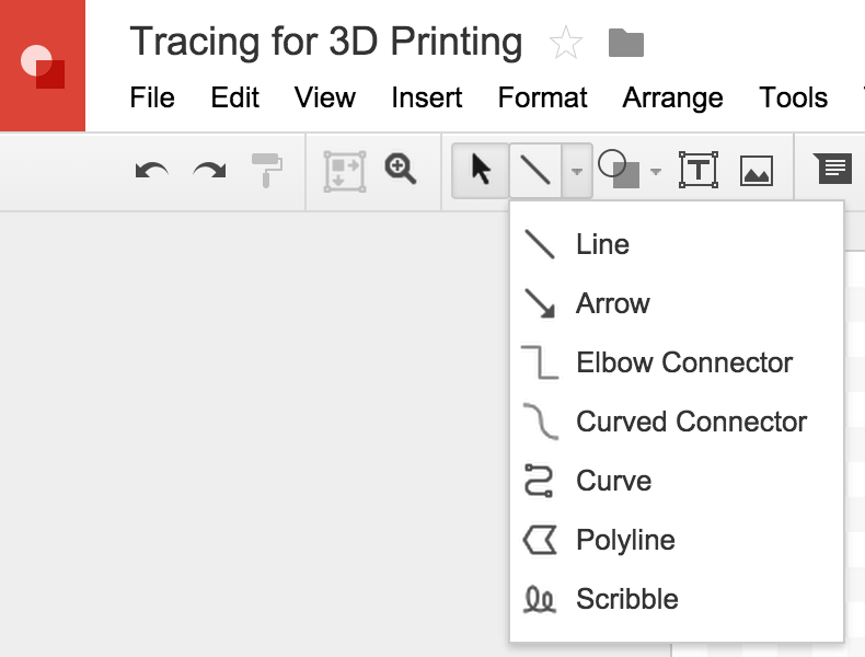


Feb 7, 2015

Google Classroom gets a 3D Printed Logo

Did I say I was finished when I finally modeled the Google Slides logo to add to the Google Docs and Google Sheets set? Well, I lied (apparently).

Google Classroom deserved some #3D Printing love - so I modeled that logo and printed off a few keychain and backpack charms. I have an idea on how to make these two color, but for now, I think Green is the best treatment. I had some issues printing these initially, as I was simultaneously testing some new slicing software (wrote about that issue separately) - but eventually I got some pretty good - not perfect - prints.

Feb 6, 2015

Slicing Software matters in 3D Printing - Cura vs Slic3r

NOTE: Post Updated (5 weeks later): I've found parameters to make CURA slicing very consistently successful - mostly thanks to the folks at LulzBot who sell great filament and provide great filament profile/config files for CURA - but also after a bunch of experimentation. I've been using CURA exclusively now and while I tweak speed and top/bottom layers on different models for different needs, I have not had a fail like the one pictured in this post since writing the original post... but leaving the post here for historical purposes.
Original post follows:

I discovered that Lulzbot seems to suggest CURA as their prefered Slicing app for generating gcode files for 3DPrinting (gcode is the language that many #3dPrinters understand). I was initially using Slic3r because that's what the Lulzbot TAZ4 manual pointed me towards. Since I'm just starting to understand the basic controls I have in Slic3r, getting a taste of CURA was a great experience - to see how it exposed and set different parameter versus the way Slic3r did.

CURA model on the left, SLIC3R on the right.
At first, I thought I had discovered gold - since one of my models generated GCode much (much!) faster than Slic3r and then the generated gcode printed extremely fast. My second try also showed improvement - printing the CURA gcode in almost half the time on a small model - and the quality was quite good.

Then I tried a new and very different model. Still very simple - some geometric shapes extruding up off a rounded courder rectangle. Sure - it happened to be the Google Classroom logo - but it's a simple one. This is where CURA not only fails me so far, but perplexes me. The top layer is practically not completed - and there is actually a shape missing. Check out the image here comparing the CURA print to the Slic3r print. See the missing shape? (it's a chalkboard eraser, by the way). The SLIC3R model is by no means perfect - I have some work to do figuring out why the top layer has gaps - but it's still much better than what CURA produced.

I still have lots (LOTS) of experimenting to do - but for now, I can see that I might have to start digging into the gcode to see what's going wrong.

Feb 2, 2015

3D modeling Google Slides icon

Once I completed the Google Docs icon and Google Sheets icons in 3D, I had no choice but to do the 3rd in the series - Google Slides.  This one was also a bit challenging in the design department. Turns out a 2D graphic design has many ways to be interpreted in 3D. You can see how I ended up with this one - offsetting the two slide frames by just a bit in the Z-axis (height) and both hollow straight through the print.

I realized that putting these icon models up on Shapeways was a great idea for people who wanted to have these but don't yet have a printer - but that I have to size them properly and separately to be clear what they are getting. I'll get to that some day very soon. Ping me here if you're actually waiting for that or want the model.

Now - You can bet that I'll be doing more product icons - but the most difficult one will be the Google Drive icon - which is 3 colors. I've been working on interlocking parts, which will be necessary for that project - stay tuned. I'll get that done in the next few days (or weeks).

Bed Adhesion while 3D Printing - more learning

While trying to model and print a simple plastic joint - a way to connect 3D Printed parts - I discovered I had a lot more to learn about basic #3DPrinting. Specifically, keeping my model stuck to the bed became a real problem during this project.

The model was taller than it was an wide or long (about a 3:1 ratio) - and I couldn't print it with the big side down on the bed because of the joint I was trying to print, which like a mortise and tenon (mortise on one side, tenon on the other) and would have had a long overhang. So printed on it's side, there would be no overhangs. Seemed perfect. I've done a taller project like this in the past, but that overall model was quite large, so still a large surface to adhere to the bed, whereas this one has quite a small surface on the bed (the whole bas is only 7mm x 40mm).

Mid-way in the print - 3 times in a row - at two different scales (I tried bigger to see if that helped - it didn't), the model would come off the bed and stick to the hot end (the extruder). The result was a half-made model with a big glob of PLA as it went for a ride with the extruder for the remainder of the print.

Other things to try in the future:
  • Perhaps the 0.15mm layer height was too small, and the extruder was too close to the previously printed layer (sticking to it and dragging it loose).
  • Perhaps a "brim" at the bottom of the model would help adhesion.
  • A hotter bed temperature may help
  • Coating the bed with a glue mixture (I read about this on support forums).
So far - I've had great success simply printing a smaller part - but that won't work for every design. If you have ideas or similar experiences, let me know.

Feb 1, 2015

Lessons from 3DPrinting multiple objects simultaneously

The 4 simultaneous copies being printed
When I started printing these mini-product-logo icons, it seemed sensible to print more than one at a time. The Slic3r App I use for creating 3D Printing gcode (the instructions which the printer understands to control every layer) has this simple "duplicate" button which made it super simple to make a "4-up" version of my model of the Google Forms product icon. BTW, The Google Forms icon was necessary , since I already did Google Docs and Google Sheets - and it was timed to be done while I had green PLA loaded :)

When I printed these - each of which is 30mm X 22mm X 4mm - I had some unexpected quality issues, which I am attributing to the simultaneous multi-item printing method. The issues simply do not occur when I print one at a time. This is a lesson worth sharing.

The Quality issues:

Curled bottoms after printing
  • Curling at the bottom of the models (in spite of a heated bed). I've never had curling on prints before.
  • "Globbiness" (there must be a technical term for this) on some edges which make them stick up or out over the edge.
  • Gaps in the top layers which make the surface not only rough, but look more like a weave than a solid.
Gaps and Globs visible in top layers
I decided to print another version of the model just one at a time - just to be sure that something else didn't change in my printer that I didn't notice. As suspected, the one-at-a-time version came out good again. Flat on the bottom, smooth on the edges and almost no gaps on the top.

COMPARISON - one printed alone, vs. one of the bad 4
Watching the printing process on both versions, I'm concluding the following: With multiple items to print, and the print head doing one layer at a time - doing layer 1 on object 1, then layer 1 on object 2, then layer 1 on object 3, etc - each object layer has too much time to dry and cool before the next layer is extruded on top. That reduces adhesion and the hot layer being laid on a too-cool layer causes the prior layer to pull up a bit. The "globbing" seems to be caused by simply too much movement between objects, whereas when there is one object, the movement of the head is always close by with less starting/sopping on extrusion. The gaps on top I can't explain too well.

I recommend trying multi-item printing in two's - figuring out an optimal level of efficiency without sacrificing quality.
COMPARISON - one printed alone vs. one of the bad 4

Project Details:

Printer:  LulzBot TAZ4
Model:  Google Forms Product Icon
Filament:  LulzBot 3mm PLA Green
Print Time:  4-copies: 85 min. 1-copy: 23 min.