Showing posts with label education. Show all posts

Mar 15, 2017

BlocksCAD 104: 3D Modeling a Multi-compartment Box with Code


BlocksCAD combines two of my favorite things: Coding and 3D Modeling. I've written about BlocksCAD before - to show the basics of how code can be used to produce 3D Models - and more recently I found a real world use for this tool that I just had to share.
Note: This is basically the 4th in a series of posts about modeling with BlocksCAD. The first is here.

Background


A while back I created a small "Battery Holder Box" - which was specifically designed to hold one type of button battery - the CR2032. This small battery has specific dimensions, so my 3D Model was made to fit that specific battery. I made a single model with specially sized compartments to hold 10 of these batteries.

About a week later, I needed another similar box to hold LR44 batteries, which are slightly different dimensions than the first - so I went through the painstaking process of reproducing the battery box to those dimensions.

Then a few weeks after that, I wanted a similar box to hold SD cards - and again, I grimaced while I considered repeating all the steps to create a specially sized box to hold a dozen SD cards. Then it struck me - I can CODE THIS!

The Power of BlocksCAD
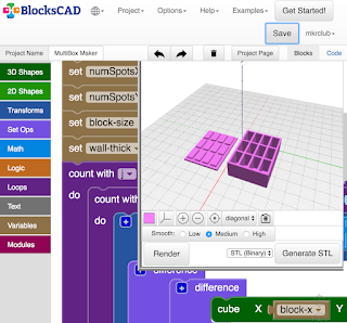

As a software engineer, I'm trained to recognize patterns like this - and it's exciting when a pattern as obvious as the above can be turned into code. That's what BlocksCAD lets me do! Using code to produce storage boxes like this, I can use parameters (variables) to change the measurements in my code, and within seconds, have practically ANY size compartment and box configuration!

How I Made AnyBox - an overview


I'm going to give you just the basics here - I won't describe every line of code (or, in this case block of code).

I start by creating ONE compartment. It's basically a hollowed out rectangle meant to hold something - a box. From there, I simply make a bunch of those compartments by repeating the same code as many times as necessary. I do this in two dimensions - so I can have, for example, 3 across and 4 down, or 1 across and 3 down - similar to what a book case might look like. Once the boxes are done, I create a TOP - with the exact configuration of n across and m down as the boxes, but with a more flat extrusion vertically.

That's the high level story - below is the detail...

Making the First Box


I start by creating ONE box, one compartment - using 3 variables - the width (X), the length (Y) and the height (Z). These measurements are the measurements of the INSIDE of the compartment that I wanted. So I basically measure the dimensions of the object I'm trying to hold in the box, and use those for X, Y and Z.

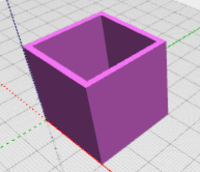
The "CUBE" block in BlocksCAD easily produces the cube with those dimensions. But I don't actually want a solid cube, I want a hollow cube.  To achieve a hollow cube, I have to use the TRANSFORM / MINUS block to subtract this cube from a slightly larger cube.

To decide how much larger that outer cube should be, I have another variable which holds the "Wall Thickness" (let's call that W here) of the box I want - and I add that to the original X, Y and Z dimensions to get the outer cube dimensions. Now the outer box can be defined as X+W, Y+W, Z+W.

Watch The Box Multiply


Now that I have ONE compartment successfully made, I can repeat the creation to make an array of boxes connected to each other to get the "cubby" look I'm aiming for. Remember the original reason for this was to hold several of the same item - button batteries in my case.

One of the great things about programming is that once you figure out how to do something, you can re-use the code to do it again. So in this case, now that I know how to make a box in the dimensions I want, I can just repeat the code to do it again. All I have to do is start the second box just next to the first, and then again, start the third box, just next to the second, etc.
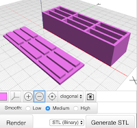
I do this with a LOOP (in coding, it is also called "iteration") to simply repeat the running of that box-creation code over and over again, as many times as the number of boxes I want. Since I want the option to have multi-dimensional cubbies - I also need a second loop around that first loop to repeat that whole set of boxes again, making another set of n boxes next to the first set of n boxes.

This is a very common pattern in coding whenever you are dealing with any sort of array - in this case it happens to be the physical creation of a multi-dimensional array object.

Making The Box Top
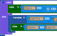


Before worrying about the complicated box top needed to cover this multi-box configuration I've now created, I need to make a TOP for that ONE compartment first. To do this, I'll use the same X, Y measurements from earlier - but I really don't need the Z, as the top will be mostly a flat top with minimal depth.

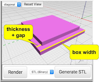
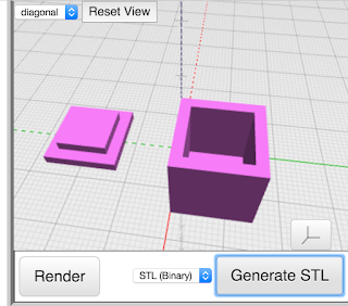
I start by creating a simple rectangle which is the same dimensions as the outer dimensions of the box - that is X+W by Y+W - which accounts for the width of the box walls again. Now, instead of hollowing out, like we did for the box, this time we want to create a slightly raised, slightly smaller panel which fits snugly inside the top of the box to hold the top on. This is done by creating another rectangle on top of the first which does NOT include the wall thickness, but just the inside dimensions X and Y.
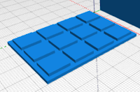
Now that we have one box compartment, we simply do the same thing we did with the box, and use a double loop to create the same number of tops connected to each other as we the box had.

Practical Addition From Testing


Along the way, of course I tested the creation of the single box, then multiple boxes in one row, then multiple boxes in an array of 2 x 3 and larger. The box was working quite well! But once I actually put objects in the box, button batteries in my case, I found a slight problem. There was no great way to get the objects OUT of the box! I had to turn over the box to get one object out, which of course dumped all the objects out.
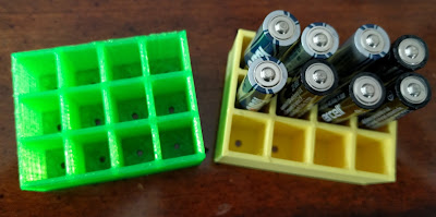
To solve this, I added one small feature - or should I say, I subtracted something. I created a small circular hole at the bottom of each compartment  (by subtracting a centered cylinder from the base of each box) - which can be used to push objects out of their compartment when needed (using a paperclip or other small pointy object). This worked just fine!

The Missing Steps Have The Real Learning


Like with all great projects, the description above doesn't really tell the whole story. There are many details left out. I don't do this to torture you, but rather because I can't remember all the smaller tweaks and adjustments I had to make to make this project work - AND, because that is where all the learning is! If I gave you every detail, you'd learn much less than if you had to figure out some of the stuff yourself.

Chances are, in doing this project yourself, you'll discover a completely new way to do this project or perhaps invent some other cool object I didn't think about!

NOTE: this is the FOURTH in a 4-part series on making models with BlocksCAD code.
Part-1 - Making 3D Models with Code Blocks (aka Intro to BlocksCAD)
Part 2 - BlocksCAD 102 - Coding a #3D Box that Grows

May 1, 2016

4th Grader Science Fair Project: Stronger 3D Printing

Every year, my kids participate in our school district's science fair. This past year (March, 2016), my 4th grade daughter - working on her 5th science fair since Kindergarten - decided to use 3D printing as her target.

After some discussion with her 3D printing-crazed dad (ahem), she decided to test the strength of 3D Printing using different print orientations.

The problem she was working on in her project was how to print stronger 3D printed objects.

She witnessed an issue I had with some hooks I printed for my pegboard a while back, and she generally thought that was an area that could use some experimentation.
Yes - I helped lead her in this direction - no doubt about it.

Her hypothesis was that the vertical layers (layered upwards along the z-axis) were not as strong as the horizontal layers printed along the x- and y-axis. She has seen many failed prints (of mine!) and has gotten familiar with the difference between the upward layers of a print and the horizontal layers.

Two test links - one horizontal, one vertical

I'll leave all the details to the slide deck - embedded below - which she made and printed for her poster board for the 2016 Science Fair.

Apr 12, 2016

5 reasons to have a 3D Printing Pen

My first 3D Pen - 3Doodler 1.0
More than a year ago, I saw my first 3D Pen - the 3Doodler - and I immediately bought it. It seemed like such a cool combination of creativity and modern technology. I had already gotten into "traditional 3D Printing" (did I really just say "traditional"?), and figured this was a natural extension of that. I didn't have any expectations of how or why I would use it, but bought it to help figure that out.

Why have a 3D Pen?


After using my 3D pen a few times, I really enjoyed creating things with it, but I also recognized that there are reasons to have them that differ a bit from the reasons for having a 3D Printer. That's what I'll outline here, a few reasons why a 3D Pen might be something you "need"...

Reason 1: Help you understand 3D Printing.

While 3D Printing is not rocket surgery, it's more fun to learn how it works by seeing it rather than reading about it or watching a video. A 3D Pen is a low cost, simple way to see 3D Printing mechanics in action. Yes, it's just plastic melting and being re-formed to harden again. But seeing it first hand - and being able to quickly create something without 3D Modeling skills or expensive machines - is cool.

Reason 2: Be Artistic in a New Way

My 2nd one - the Scribbler 3D Pen
Kids - and bigger people - often love making things. Crayons, markers, paint, yarn and fabric, even duct tape - it's all fun. But how often is there a NEW medium to create things? Not often. Melting plastic and reforming it into a new thing - now that's NEW - that's COOL.

Reason 3: It's Easy.

Making 3D objects with wood is amazing, but very hard, requiring many tools, perhaps dangerous electrical tools, and very time consuming.  Paper machè is great and simple - but it's messy! 3D Pens are easy to set up, take almost no time to get going, have minimal training with very small danger risks (watch the hot end!) and super easy to clean up. Learning how to do it is easy too! In a short session, kids can see results and even collaborate by building different parts of a larger model.

Reason 4: It's Cheap(er).

A great 3D Pen costs about $100 (although I actually got my Scribbler 3D Pen for $69, even though they now seem to be no less than $99). The PLA filament is also very cheap - about $20 for a whole roll (and you can try to calculate how much a printed object costs). A good 3D Printer costs about $500-$1000, and a better one costs more like $2000.

some experimental creations ("art")

Reason 5: Practice Experimenting and Failure

If you think creating something with a pen or crayon that you would call "Art" is difficult, well, just imagine trying that in three dimensions ;)

One thing I love about all arts and crafts is the practice it gives us - as kids and adults - in trying new things, in experimenting, in failing and trying again! Experimenting is such an important step in innovating, and that's why I love all kinds of art for EVERYONE. The 3D Pen is a great tool for this sort of practice - and is a fun alternative that spurs people's interest in something they may have never tried before. That's a good thing!

One reason to NOT get a 3D Pen.


Do not get a 3D Pen as an alternative to a 3D Printer.

not so precise mini-building
It is not at all the same thing. A 3D Printer is basically a robot which melts plastic and forms it into an object that has been modeled with 3D Modeling software. While that type of 3D PRINTING is not artistic - the 3D Modeling part can be VERY artistic. It's just that the actual printing process is not the artistic part when using a 3D Printer.

Conversely, the 3D Pen is NOT a good way to precisely create a 3D object for functional use. It is very hard to create an object of precise measurements or with straight edges or smooth, measured curves.

The comparison of 3D Pens to 3D Printers is analogous to comparing drawing by hand to printing with an inkjet printer - the first being artistic, the second being functional. Bat, as in 3D Printing, an inkjet printer required perhaps some artistic process first, before the actual printing step.

Here's what you'll have a lot of...
One other important point:  Because using the 3D Pen means having it closer to your face while you use it, you should ONLY use PLA - NOT ABS. It has been found that ABS Plastic often has harmful fumes, while most PLA does not.

Engadget wrote a post on this recently, which I try to share with everyone I know who does 3D Printing under any conditions - but I think it is even more important for 3D Pen use because of the likelihood of breathing in fumes.


Apr 10, 2016

Expanding Creativity With A 3D Printing Pen

3D Pens have popped up everywhere. Ok, not everywhere - like there are none in my sock drawer - but certainly in stores and online where, just a year ago, you would not have seen them.

If you have already tried a 3D Pen or bought one or generally know about them, you can stop reading now. If you wanted to understand the basics of what they are, this short post should help you.

What is a 3D Pen?


A 3D Pen is an electric tool which lets you create things out of plastic. It's a creative tool - perhaps it could even be called a toy. It is what I would call a modern version of play-dough.

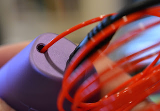
Most 3D Pens take a strip of plastic "filament" into one side, heats it up to around 175 degrees Celsius (347 Fahrenheit!) and forces it out of the other side (tip) of the "pen" in a narrow stream allowing you to "draw" with it.

As the plastic dries, it hardens back into firm plastic, remaining in whatever form you created. If you've ever decorated a cake with one of those pastry bags, you pretty much know how to use a 3D Pen.

The plastic used is typically the same as that used by 3D Printers. PLA is the best option, as it has less harmful (or worrisome) fumes and melts at a slightly lower temperature (although, 345F is still pretty darn hot!). Some 3D Pens expect you to use their own "plastic sticks" - like the 3Doodler - but I prefer pens which are friendly to the same filament I'm using with my 3D Printer, so I don't have to buy separate material.

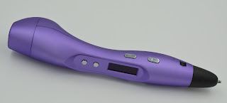
Scribber 3D Pen has a clear screen to show the settings

Controlling the 3D Pen


There are some basic controls on most 3D pens.

Temperature is the most important, as different plastic requires different temperatures.

Speed is another option on some pens, so you can control the rate at which the melted plastic comes out of the tip.

Then there's the motion - all pens which use plastic filament have both a forward (for drawing) and reverse (for removing un-used filament) - which allows you to "draw" or stop as you want to. That's pretty much it. Simple.

World's First, and My First - 3Doodler


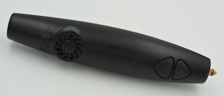
The 3Doodler 1.0 - the original
The first 3D Pen I ever saw - in September 2014 at the MakerFaire in NYC - and apparently the first one ever invented, was the 3Doodler.

That first version of the 3Doodler, which I bought pretty much at first sight, was good - but not excellent - which is pretty expected given it was the "world's first". It was loud (it even has a fan in it) and bulky and had inconsistent reliability in my experience and clogged a couple of times too.

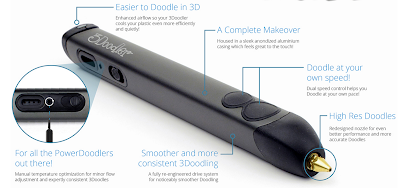
The 3Doodler 2.0 - from 3Doodler's site
That said, the first early 3Doodler helped me understand the concept well and frankly, amazed me.

Since then, the 3Doodler company greatly improved on their original design and now sells their second version which I don't own yet. IT has been considered by others to be a huge improvement over the first - Less bulky, quieter, more reliable.

I'll definitely try the version 2.0 3Doodler eventually, and I have the utmost respect for this company's founders, as they really innovated and broke new ground, defining this whole product category. You can now buy the 3Doodler in almost every innovative electronic-friendly toy or game shop and even in Brookstone and other high-end retailers.

3D Pens Galore


Scribbler 3D Pen
With 3Doodler's success in this new product category, it was inevitable that others would follow to create similar products. I've seen all sorts of variations on this theme now, but most are just basic knock-offs.

I decided to try one called the "Scribbler 3D Pen" (3rd generation). It was highly rated on Amazon and - at the time - was on sale for $69. (As of this writing, it is $99 in all the listings I could find).

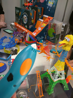
I saw one completely new 3D Pen design at the NYC Toy Fair this past February called CreoPop - which uses liquid "ink" without heat - rather it uses LED lights to dry the ink as it emits from the pen's tip. This also seemed to allow more option in material with glow-in-the-dark, neon and more colors. This looked cool, but I haven't had a chance to try it first hand.

New 3D Pen version for kids coming


3Doodler Start and some creations
3Doodler is also showing and taking pre-orders for a completely new product called the 3Doodler Start.

This version operates at a much lower temperature with completely new filament which is non-toxic, making the whole kit much safer for younger kids!

I saw this product at the NYC Toy Fair in February 2016, and was VERY impressed. I expect this product to be a huge success for kids and schools if it proves to be reliable with reasonably priced filament. Nice to see 3Doodler continuing to innovate in 3D Pen Printing.

Conclusion


If you love crafts and Maker projects, and often have the opportunity to work with kids to encourage them to experiment and try new things - get a 3D Pen. Make no mistake - this tool is not for creating precision objects as you might do with a 3D Printer. This tool is mainly for creativity and art.

I haven't worked with enough different models to absolutely pick which is best and recommend a "winner" - but I will say that I've had great luck so far with the Scribbler 3D Pen myself and have heard good things about 3Doodlers 2.0 version.

Check ratings on Amazon and Google Shopping to get a broader opinion before buying.

Mar 26, 2016

BlocksCAD 103: Making the fitted Box Top

This is the third in a 3-part series introducing BlocksCAD - a 3D modeling tool which uses block coding to create objects. If you haven't yet read the first two, check them out first.
Part 1 - BlocksCAD 101 - Making 3D Models with Code Blocks
Part 2 - BlocksCAD 102 - Coding a #3D Box that Grows

In this part 3, you'll see how using parameters to make a box, makes it simple to make a fitted box top. With this method, a simple change in ONE value in your code will change the dimensions of the box AND the top!

Design Goals


No matter how you create your 3D Models, you should always think first about your design goals. For this box plus matching box top project, we want the box top to be flush with the outside of the box, and we want it to have a protrusion on the inside to let it sit perfectly in place over the opening of the hollow box. In essence, we want a rectangle top, with a smaller rectangle protruding from the bottom which matches the inner dimensions of the hollow top of the box.

Using Values To Create Objects


In Part 2, we created a box of a specific size using a variable we called "block-size". We also declared that we wanted the thickness of the walls of that hollow box to be determined using the variable we called "wall-thick". Now that we're looking to make a fitted top for that box, those dimensions will come in handy.

Start With Basic Shapes


Let's think about our box top as two rectangles - one which is the same width and length as outside of the box itself, one one smaller rectangle sitting on top of the first, centered, which matches the smaller dimensions of the hollow part of the box. We're printing this box top upside down, which is why the smaller rectangle is on top.

The thickness of the box top (the height when printing - also known as the z-axis value) can match the thickness of the walls of the box - so that will use the "wall-thick" variable value. The thickness (depth) of the protruding, smaller rectangle can also use that thickness value. Simple! So the first rectangle is created using the following CUBE block.


The smaller rectangle is slightly trickier. It's size is basically meant to be the same size as the INNER dimensions of the hollow box, so that would be calculated as the outer dimension, minus the thickness of the walls. Since there is a wall on each side of the x dimension and y dimension, that means we have to subtract TWO TIMES the wall thickness from the block size to get the inner dimension of the smaller rectangle. Let's create a new variable to calculate that size and call it "sm-block". That variable, and the subsequent creation of the smaller block is shown below:


Making The Top Fit Better


If you've ever printed 3D objects that are meant to fit together, you know that a 10mm part will NOT fit into a 10mm hole. There is always the need for additional gap between parts to make them fit. The value of this "coding objects" method is that we can code that gap - and adjust it for different materials or different printers. On my Polar3D printer, I know that I usually need about 0.35mm gap on either side for a loose fit - which is about 0.7mm total on each dimension (I made it 0.75mm).

Now in the X and Y dimensions of that smaller rectangle, I subtract the value of "gap-mm" to allow for the proper fit. If I find the fit to be too tight, I simply increase that value to give a bigger gap.

Put The Shapes Together

Now that we have the two basic shapes, we can put them together to construct the box top.
The most powerful code blocks in BlocksCAD are in the "SET OPS" group (Set Operations). For this object, we need to combine the two distinct rectangles using the "UNION" block. This is a pretty common operation, which combines two shapes into one.
Notice that before combining the second shape (the smaller rectangle) with the first, we need to shift it up a bit so that it sits on top of the first shape. That's where the "TRANSLATE" code block comes in. We shift the position on the Z-Axis by the thickness of the first rectangle.


The code shown above s the complete code block which makes the Box Top - but notice that it relies on the variables from the prior examples where we made the box itself. Specifically, the block-size and wall-thick variables.

The finished product in two sizes - 10mm and 30mm
Hopefully this three-part series gave you a sense not only of how to use BlocksCAD, but the value of using it. It's super fun to play around with BlcoksCAD, but more importantly, it's useful.

NOTE: this is the third in a 3-part series on making models with BlocksCAD code.
Part-1 - Making 3D Models with Code Blocks (aka Intro to BlocksCAD)
Part 2 - BlocksCAD 102 - Coding a #3D Box that Grows

Mar 20, 2016

3D Printed Easter Bookmarks

This coming Sunday, many will celebrate Easter - and it just wouldn't be fair to let them celebrate without an Easter-themed 3D Printed bookmark to spread the joy!

This whole trend started on Superbowl (tm) Sunday, then Valentine's Day, then We Hate Paper day (which is actually every day), and a bunch more.

Given that I've described so much about how I've created those projects in prior posts, I won't bore you with the details on this one. I'll just share the model (at the bottom of the post).


Imagine the looks on the kids faces, when they look in their easter baskets, and instead of delicious chocolate goodies, they find a pile of 3D Printed plastic bookmarks in the image of decorated Easter eggs! Oh Joy!

"Thanks mom and dad! Now seriously, where is the chocolate?"

The Model


You can find this model on Thingiverse - along with the many other bookmark designs I've created. Enjoy!


Mar 16, 2016

BlocksCAD 102: Coding a 3D Box That Grows
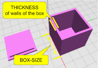
Using code to create 3D Models give you the benefit of customization - the ability to take a set of parameters (values) which influence how the model looks. In the introductory BlocksCAD lesson, we learned how to define a variable and then use the value stored in that variable to change some aspect of the 3D Model. In that case we changed a single dimension of a basic rectangle model. [note: this is the 2nd in a 3 part lesson - if you missed it, go back to the prior lesson first]

In this lesson, we'll use that same technique to do something more useful. We'll write a program which creates a hollow box in any size, and later we'll give it a fitted top to match.

Some Programming basics - Inputs and Outputs


Almost all programs take some sort of "inputs" - also known as "parameters" - and then use those inputs to influence the results of the program - the "outputs".

For example - when you use Google Search, the inputs are the search terms you enter. The outputs are the search results.

When you write your own program, you get to decide what the inputs and outputs are. In BlocksCAD, the output is a 3D Model - so you decide what inputs should be accepted to influence that 3D Model that is created.

When creating a 3D model of a hollow box with a fitted top, what aspects of that box might you want to influence, and make those your inputs? Think about it a bit... I'll wait.

The Box Which Adjusts To Fit Anything


The aspects of the box I would like to control with my program are the size of the box and the thickness of the walls of the box. This way, whether I want a box to hold a guitar pick, or a box to hold a furry bunny - I can use the same program to generate the model - by just giving it different inputs to control the size! (and no, I would not recommend storing a furry bunny in a 3D printed box).

To achieve this, we will build a program using the coding blocks which use variables that can easily be changed to adjust all the aspects of the model which are dependent on them.

Writing the Code to Make The Box

First - let's plan out how to make a hollow box. The way this is often done in 3D Modeling is to create a cube which is the size of the outer dimensions of the box you want - and then create a smaller cube which can be "subtracted" from the inside of that first cube to hollow it out.
Great - and EASY!

We first decide what our Variables are. We pretty much already actually did that above - so let's just call them: box-size and thickness.  Then we'll use those in modeling the cubes we need.

> From the "VARIABLEs" category, drag over a "SET ITEM TO" block and create a "new variable" (in the drop down next to "Item") - and call the first one "block-size" - then do another variable called "thickness".

> From the MATH category, drag over a "0" number block and drop it into the "SET block-size TO" block - and change the value to 30 (we're starting with a 30mm box). Do the same with "thickness", but change that value to "2" (we're starting with 2mm wall thickness).

> Drag a "CUBE" block over.

> From the VARIABLES area, drag over the "block-size" block - which gives the VALUE of that block-size variable - and put it in the "X" component of the CUBE block. Then do the same again for "Y" and "Z". All of the 3 dimensions will be the same - 30mm.

At this point, you can test this program by just clicking the RENDER button. You should see a 30mm x 30mm x 30mm block appear in the rendered model window!

Making the Box Hollow


There are a set of very important coding blocks in a category called "SET OPS" (Set Operations) which let you do things like merge two shapes, or take the difference between two shapes. The "DIFFERENCE" block is the one we'll need here to hollow out the box - taking the difference between our original box and a slightly smaller box. If you're familiar with TinkerCAD, you know this as the "Hole" method. In Autodesk 123D Design, it is the "Combine" / "Subtract" feature.

First - let's make the smaller box. The measurement of this smaller box will basically be the size of the larger box (block-size) minus two times the thickness of the walls (once for each side). So the 30mm original box, needs a smaller box which is 30 - (2 x 2) or 26mm on the X and Y dimension - and 30 - 2 on the Z (height) dimension, so that the top of the box actually is open (we don't after all want a hollow box with no openings - we want the top to be open!)

Let's do the coding blocks now - using a new variable, some math and some transformations...

> from the VARIABLES category, create a new variable called sm-block.
This is the finished correct code for the Hollow Box.

> from the MATH catogory, take a math block which does ADDITION - then use the dropdown arrow to change that to SUBTRACTION. Take another of those same blocks again and make the second one MULTIPLICATION.

> Put the values in the blocks as shown to become the equation we described above (block-size - (2 x thickness)) and put that into the SET sm-block TO block.

> From the 3D Shapes category, take a CUBE block and set all the dimensions to the value of the "sm-block" variable.

OOPS! the smaller box was not centered
> From the SET OPS category, take a DIFFERENCE block and drag your original CUBE into the top slot, and the smaller cube into the bottom slot.

Now hit RENDER to test! OOPS! The two boxes clearly were not aligned! So the result of the subtraction did not turn out as planned.  To fix that, we'll move the smaller box to center it on the larger box - moving it by one wall thickness measurement on the x, y and z axis.

> from the TRANSFORM category, grab a TRANSLATE (move) block and set all the paarmeters to the value of the "thickness" variable.
> Put the smaller CUBE block inside that TRANSLATE block.
> Move the TRANSLATE block into the second slot of the DIFFERENCE block.

NOW test again... and BAM! You should see your hollow box.


This is Where The Magic Happens


Now - let's change the size of the box - while keeping the thickness of the walls at 2mm.
Pay attention or you'll miss it....
>  Change the value in the "Set block-size to" block to 50mm
>  Click the RENDER button.

You should now see a larger box! Play around - this helps to test your code and, assuming it works, gives you some satisfaction! Change the value of "thickness" (to 4 or 6) and click render. Those are some thick walls! Good thing you aren't stuck with that :)

In the next lesson, we'll make the Box Top - something that uses mostly the dimensions of the box but with a slight adjustment to allow for a perfect fitting top.


NOTE: this is the second in a 3-part series on making models with BlocksCAD code.
Part-1 - Making 3D Models with Code Blocks (aka Intro to BlocksCAD)

Mar 15, 2016

BlocksCAD 101 - Making 3D Models with Code Blocks

Most people say there are two ways to create digital 3D Models - 1) manually, using CAD (Computer Aided Design) and 3D Modeling software/apps - and 2) by scanning real-world objects with a camera or other scanning equipment to automatically interpret them into 3D Models.

But there's a third way to create 3D Models - you can CODE them.

Coding to create 3D Models


You can write a program which gives the computer commands which creates 3D objects. If you're a programmer, you can try something called OpenSCAD - which is basically a programming language which defines 3D objects. If you're not yet a programmer, and want to (or are willing to) learn some programming basics that pretty much anyone can learn, you can try BlocksCAD.

Overview of BlocksCAD


BlocksCAD is a block programming tool - similar to those used to teach coding to kids - which has commands and tools to create 3D Objects and is super easy to learn for kids or adults. It is available on the web, through your browser, so no programs to download and it is very friendly for Chromebooks.

BlocksCAD was developed by the Massachusetts-based Einsteins Workshop - a learning organization for kids. It combines aspects of doing simple programming (aka coding) with aspects of simple 3D Modeling. The results of BlocksCAD code are 3D Models which can be downloaded in .STL format for 3D Printing or for use in other programs which import .STL files (almost all do).

BlocksCAD interface - 3 main parts

Get Started in BlocksCAD


The BlocksCAD interface consists of 3 main parts:
1 - Library of available blocks
2 - YOUR blocks (that's your code)
3 - 3D Model Viewer

The process of creation is quite simple:

> Find the blocks you need from the Library of available blocks. Each category on the left side expands out to reveal all the blocks available in that category.

Sample flow - choosing the SPHERE block, and rendering it.
> Drag the block you need into your code area. Later you'll see how they snap together to form groups of commands - for now start simple.

> Adjust the values used in the blocks as needed. Each block has it's own options relevant to that command - for example - the Sphere block asks for the radius of the sphere.

> Click "Render" in the 3D Model Viewer to see the results!

Creating your first Coded 3D Model


Let's keep this really simple to start. Let's create a rectangle. Pay attention - this is so quick you might miss it....
> Click on the "3D Shapes" category on the left side.

> Grab the "CUBE" block and drag it to the main screen area (in the center).
> Click "RENDER" on the viewer window.

> DONE. You just coded your first 3D Model!

Notice that the CUBE block has 3 values and one option. The X, Y and Z values define the size of each of those dimensions. You can click on those and change them. Click RENDER after each change to see what they do. The "Not Centered" option could have been changed to "Centered" to put the model in the middle of all axis.

Using a Variable to Modify Your Shape


Now let's use a "variable" - a placeholder which has a value - to help define the dimensions of your shape. In this case, we'll define the X-Dimension of your cube (actually, rectangle).

> Go to the "VARIABLE" category
> Drag the "Set Item To" block into your blocks space and connect it to the top of the CUBE block. It should snap into place.
> Let's name the variable better to make it something more relevant. Use the dropdown on "Item" in the block to select "New Variable" and name it "xSize". This will represent the value in millimeters of the X-dimension of the cube.
> Go to the "MATH" category and drag the "0" value block (the tiny blue one on the top) into the empty space in that "Set xSize To" block.
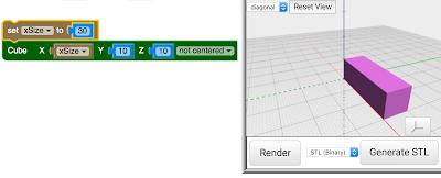
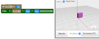
> Change the value in the "0" block to "5" for now.
> In the VARIABLE category again, drag out the "xSize" block - which represents now the value stored in the variable you named "xSize".
> Drop that "xSize" value block into the cube block where the "X" value is shown (there's a "10" there now). Dropping this block will push the other block out of there. you can click that "10" block once and then hit the "delete" key on your keyboard to delete it.

You now have a simple way to model a cube with any X dimension simply by changing the value of the xSize variable. Not super useful yet - but later you will see why using variable gives you power to easily make adjustable models for customization without re-drawing models.

Advantages of Coding 3D Models


The hollow box example you will learn in the next post
The idea behind coding 3D Models is to give an automated way to create custom objects. While plenty of 3D Models are actually artistic and benefit from human creativity, some models are simply functional and can be more quickly created using rules and precise measurements. That's where coding helps.

Let's take scaling for example (making a model larger or smaller)...
Most 3D Modeling apps and even Slicer apps make it easy to scale a 3D model to get larger or smaller sizes. But, sometimes, simple scaling can not achieve the desired outcome. For example, if you have a simple, square, hollow, open-top box which is 20mm square with walls which are 2mm thick. If you want a 40mm box, you can easily scale the model to 200% before printing. But then the walls of the new box will be twice as thick - 4mm instead of 2mm. That is not likely what you wanted. Most modeling apps even let you constrain the scaling to X, Y or Z axis - but in this example, there is no way to avoid the change to the wall thickness.

With Coding, I could easily separate the thickness of the walls of this box to be it's own setting (it's own VARIABLE!). This, in fact is the exact example which we will review in the next post - so stick around! In the next lesson, we'll learn how to make a 3D Hollow Box that Grows!

NOTE: this is the first in a 4-part series on making models with BlocksCAD code.
Part-1 - Making 3D Models with Code Blocks (aka Intro to BlocksCAD)
Part 2 - BlocksCAD 102 - Coding a #3D Box that Grows