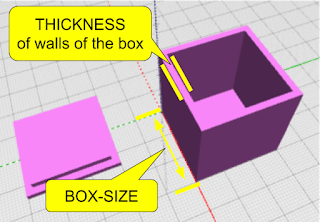
 Using code to create 3D Models give you the benefit of customization - the ability to take a set of parameters (values) which influence how the model looks. In the introductory BlocksCAD lesson, we learned how to define a variable and then use the value stored in that variable to change some aspect of the 3D Model. In that case we changed a single dimension of a basic rectangle model. [note: this is the 2nd in a 3 part lesson - if you missed it, go back to the prior lesson first]
In this lesson, we'll use that same technique to do something more useful. We'll write a program which creates a hollow box in any size, and later we'll give it a fitted top to match.
Some Programming basics - Inputs and Outputs
Almost all programs take some sort of "inputs" - also known as "parameters" - and then use those inputs to influence the results of the program - the "outputs".
For example - when you use Google Search, the inputs are the search terms you enter. The outputs are the search results.
When you write your own program, you get to decide what the inputs and outputs are. In BlocksCAD, the output is a 3D Model - so you decide what inputs should be accepted to influence that 3D Model that is created.
When creating a 3D model of a hollow box with a fitted top, what aspects of that box might you want to influence, and make those your inputs? Think about it a bit... I'll wait.
The Box Which Adjusts To Fit Anything
The aspects of the box I would like to control with my program are the size of the box and the thickness of the walls of the box. This way, whether I want a box to hold a guitar pick, or a box to hold a furry bunny - I can use the same program to generate the model - by just giving it different inputs to control the size! (and no, I would not recommend storing a furry bunny in a 3D printed box).
 To achieve this, we will build a program using the coding blocks which use variables that can easily be changed to adjust all the aspects of the model which are dependent on them.
Writing the Code to Make The Box
First - let's plan out how to make a hollow box. The way this is often done in 3D Modeling is to create a cube which is the size of the outer dimensions of the box you want - and then create a smaller cube which can be "subtracted" from the inside of that first cube to hollow it out.Great - and EASY!
We first decide what our Variables are. We pretty much already actually did that above - so let's just call them: box-size and thickness. Then we'll use those in modeling the cubes we need.
> From the "VARIABLEs" category, drag over a "SET ITEM TO" block and create a "new variable" (in the drop down next to "Item") - and call the first one "block-size" - then do another variable called "thickness".
> From the MATH category, drag over a "0" number block and drop it into the "SET block-size TO" block - and change the value to 30 (we're starting with a 30mm box). Do the same with "thickness", but change that value to "2" (we're starting with 2mm wall thickness).
> From the MATH category, drag over a "0" number block and drop it into the "SET block-size TO" block - and change the value to 30 (we're starting with a 30mm box). Do the same with "thickness", but change that value to "2" (we're starting with 2mm wall thickness).
> From the VARIABLES area, drag over the "block-size" block - which gives the VALUE of that block-size variable - and put it in the "X" component of the CUBE block. Then do the same again for "Y" and "Z". All of the 3 dimensions will be the same - 30mm.
At this point, you can test this program by just clicking the RENDER button. You should see a 30mm x 30mm x 30mm block appear in the rendered model window!
Making the Box Hollow
There are a set of very important coding blocks in a category called "SET OPS" (Set Operations) which let you do things like merge two shapes, or take the difference between two shapes. The "DIFFERENCE" block is the one we'll need here to hollow out the box - taking the difference between our original box and a slightly smaller box. If you're familiar with TinkerCAD, you know this as the "Hole" method. In Autodesk 123D Design, it is the "Combine" / "Subtract" feature.
First - let's make the smaller box. The measurement of this smaller box will basically be the size of the larger box (block-size) minus two times the thickness of the walls (once for each side). So the 30mm original box, needs a smaller box which is 30 - (2 x 2) or 26mm on the X and Y dimension - and 30 - 2 on the Z (height) dimension, so that the top of the box actually is open (we don't after all want a hollow box with no openings - we want the top to be open!)
Let's do the coding blocks now - using a new variable, some math and some transformations...
> from the VARIABLES category, create a new variable called sm-block.
 |
| This is the finished correct code for the Hollow Box. |
> from the MATH catogory, take a math block which does ADDITION - then use the dropdown arrow to change that to SUBTRACTION. Take another of those same blocks again and make the second one MULTIPLICATION.
> Put the values in the blocks as shown to become the equation we described above (block-size - (2 x thickness)) and put that into the SET sm-block TO block.
> From the 3D Shapes category, take a CUBE block and set all the dimensions to the value of the "sm-block" variable.
 |
| OOPS! the smaller box was not centered |
Now hit RENDER to test! OOPS! The two boxes clearly were not aligned! So the result of the subtraction did not turn out as planned. To fix that, we'll move the smaller box to center it on the larger box - moving it by one wall thickness measurement on the x, y and z axis.
> from the TRANSFORM category, grab a TRANSLATE (move) block and set all the paarmeters to the value of the "thickness" variable.
> Put the smaller CUBE block inside that TRANSLATE block.
> Move the TRANSLATE block into the second slot of the DIFFERENCE block.
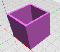
 NOW test again... and BAM! You should see your hollow box.
This is Where The Magic Happens
Now - let's change the size of the box - while keeping the thickness of the walls at 2mm.
Pay attention or you'll miss it....
> Change the value in the "Set block-size to" block to 50mm
> Click the RENDER button.
You should now see a larger box! Play around - this helps to test your code and, assuming it works, gives you some satisfaction! Change the value of "thickness" (to 4 or 6) and click render. Those are some thick walls! Good thing you aren't stuck with that :)
In the next lesson, we'll make the Box Top - something that uses mostly the dimensions of the box but with a slight adjustment to allow for a perfect fitting top.
Part-1 - Making 3D Models with Code Blocks (aka Intro to BlocksCAD)
Part 3 - BlocksCAD 103 - Making the Fitted Box Top
Part 4 - BlocksCAD 104 - 3D Modeling a Multi-Compartment Box with Code
Part 4 - BlocksCAD 104 - 3D Modeling a Multi-Compartment Box with Code


No comments:
Post a Comment