- Make models which cannot be printed in a single print due to overhanging sections or other complexities which are difficult in Fused Filament Fabrication (FFF) printing.
- Make models which have adjustable and moving parts using hinges and rotary joints.
- Make multi-color models, where different parts can be printed in different colors.
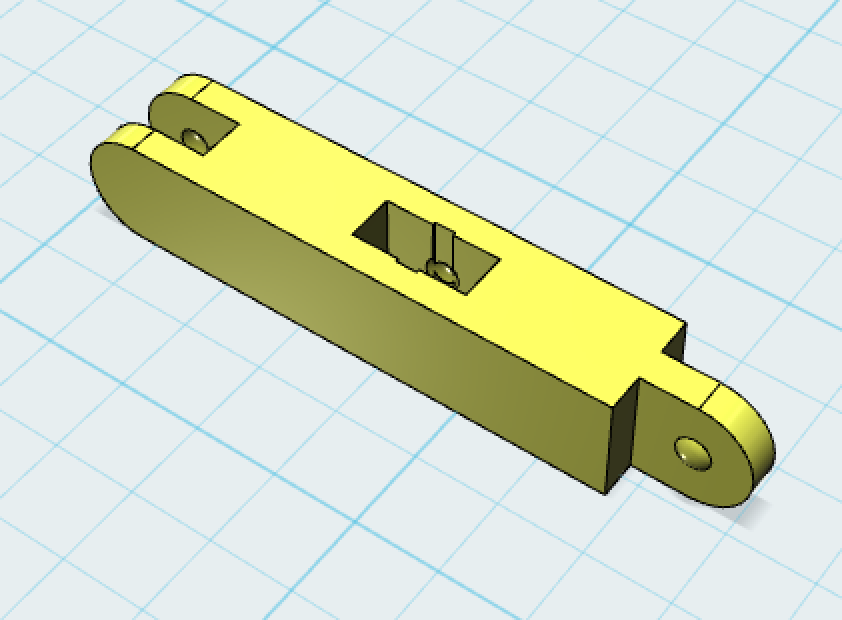 |
| The final object with center mortise and rounded tenon |
A mortise-and-tenon joint is basically a fitting where one end - the mortise - is a hole or gap, where the other end fits perfectly to fill that hole or gap - making a tight enough fit to hold. It seemed to me that the best way to get this effect was to use "subtractive" modeling (In Autodesk 123D Design, that is called the "Combine" / "Subtract" command). This means first modeling the tenon, then subtracting that tenon from the 2nd object to make a perfect mortise which fits that tenon.
The tenon in my experiment was going to be just a rectangle stick - and the mortise, therefore, the inverse of that - a rectangle hole the same exact dimensions.
Making the Tenon
 |
| the tenon with locking button |
I wanted to add a bit of a "locking" mechanism to this joint I added a very small bulging "button" on either side of the tenon. I made this by simply overlapping a sphere with a diameter slightly larger than the width of the tenon onto the tenon itself, and then combining the sphere with the tenon.
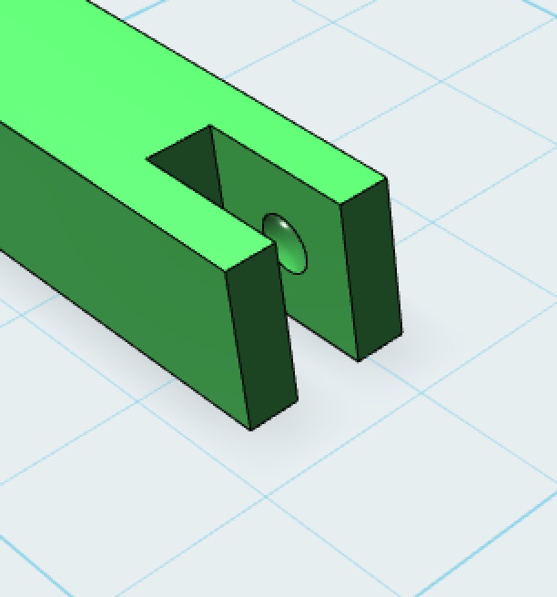
Making the Mortise
 |
| using the tenon to create the almost perfect mortise |
Now we have a perfectly (too perfectly) fitting tenon and mortise. After that subtraction, the mortise is exactly the dimensions of the tenon which will fit into it - but with zero clearance, which means in real life the tenon will be way too tight to actually fit. I used a simple method of adjusting the tenon and/or mortise to make the parts fit together well. I select the faces of the tenon which will be inside the mortise, and I push them in (toward the center) by approximately 0.4 - 0.5 mm on each side - giving ultimately 0.8 - 1mm of clearance on the horizontal and/or vertical dimension of this joint. I also reduce the bulge/button by that amount if the face reduction didn't do that automatically.
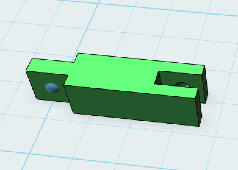
 |
| The mortise with inverted locking button to grab the tenon, after expanding each side just a bit |
Notice also, that I wanted a two-sided part, with a mortise on one side and a tenon on the other, which would give me flexibility to make continuous connections (like a construction toy!). So, I
replicated the main shape which had the tenon on one side and made the mortise on the back side of that using the replicated shape as the subtraction shape.
replicated the main shape which had the tenon on one side and made the mortise on the back side of that using the replicated shape as the subtraction shape.
Dimensions of the Mortise and Tenon
The fit of the resulting joint depends on the quality and precision of the print. That 0.8-1mm of clearance worked well for me on tenons of approx 2mm - 8mm for objects of about 50mm - 100mm long/wide. You'll likely have to experiment to get measurements precise for your needs.
Adjustments & Features
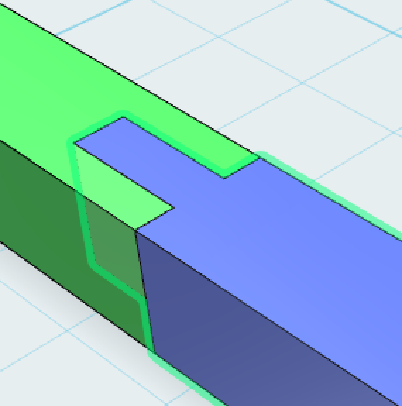
 |
| The almost final part, before rounding the tenon and adding the second mortise in the center |
I also wanted to be able to insert parts into the center of other parts, so I added an additional mortise in the middle of each. Notice I had to add a small channel to make it easier for that button on the tenon to slip into the center mortise.
Some details of the experimental joint
My experimental part was 30mm x 5mm x 5mm - with the mortise/tenon on the 5mm x 5mm end. The tenon ended up being 5mm (covering the total width) by approx 1.66mm (one third of the 5mm width to make each side of the tenon also 1.66mm).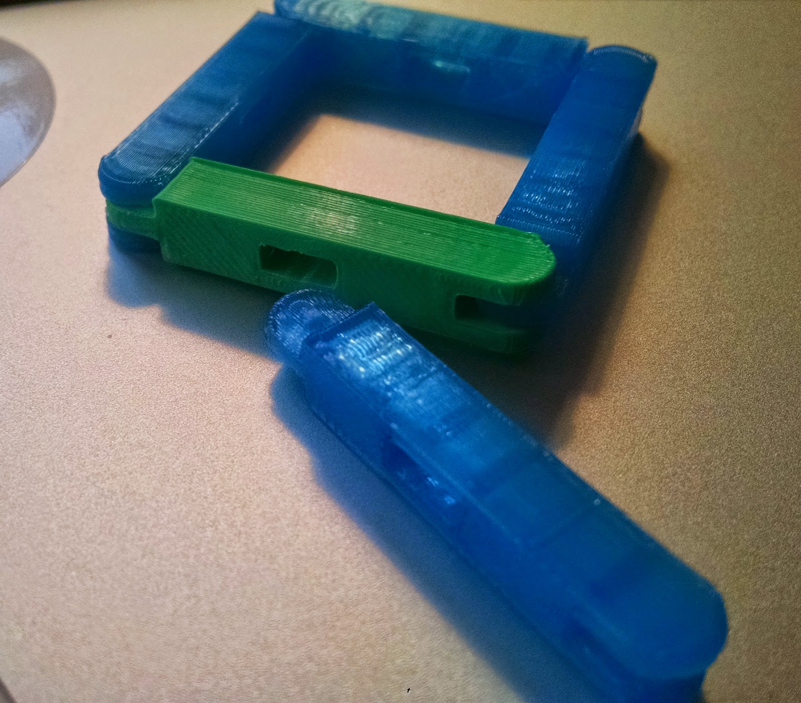 |
| Here are 5 parts, 4 of which are snapped together into a square |
Hello!
ReplyDeleteI'm looking for your Mortise and Tenon model! It would be very good for me if you are ok to share it, maybe on thingiverse.com (I follow you)
Great designs, grats :)
Julien.