Mar 20, 2016

3D Printed Easter Bookmarks

This coming Sunday, many will celebrate Easter - and it just wouldn't be fair to let them celebrate without an Easter-themed 3D Printed bookmark to spread the joy!

This whole trend started on Superbowl (tm) Sunday, then Valentine's Day, then We Hate Paper day (which is actually every day), and a bunch more.

Given that I've described so much about how I've created those projects in prior posts, I won't bore you with the details on this one. I'll just share the model (at the bottom of the post).


Imagine the looks on the kids faces, when they look in their easter baskets, and instead of delicious chocolate goodies, they find a pile of 3D Printed plastic bookmarks in the image of decorated Easter eggs! Oh Joy!

"Thanks mom and dad! Now seriously, where is the chocolate?"

The Model


You can find this model on Thingiverse - along with the many other bookmark designs I've created. Enjoy!


Mar 16, 2016

BlocksCAD 102: Coding a 3D Box That Grows

Using code to create 3D Models give you the benefit of customization - the ability to take a set of parameters (values) which influence how the model looks. In the introductory BlocksCAD lesson, we learned how to define a variable and then use the value stored in that variable to change some aspect of the 3D Model. In that case we changed a single dimension of a basic rectangle model. [note: this is the 2nd in a 3 part lesson - if you missed it, go back to the prior lesson first]

In this lesson, we'll use that same technique to do something more useful. We'll write a program which creates a hollow box in any size, and later we'll give it a fitted top to match.

Some Programming basics - Inputs and Outputs


Almost all programs take some sort of "inputs" - also known as "parameters" - and then use those inputs to influence the results of the program - the "outputs".

For example - when you use Google Search, the inputs are the search terms you enter. The outputs are the search results.

When you write your own program, you get to decide what the inputs and outputs are. In BlocksCAD, the output is a 3D Model - so you decide what inputs should be accepted to influence that 3D Model that is created.

When creating a 3D model of a hollow box with a fitted top, what aspects of that box might you want to influence, and make those your inputs? Think about it a bit... I'll wait.

The Box Which Adjusts To Fit Anything


The aspects of the box I would like to control with my program are the size of the box and the thickness of the walls of the box. This way, whether I want a box to hold a guitar pick, or a box to hold a furry bunny - I can use the same program to generate the model - by just giving it different inputs to control the size! (and no, I would not recommend storing a furry bunny in a 3D printed box).
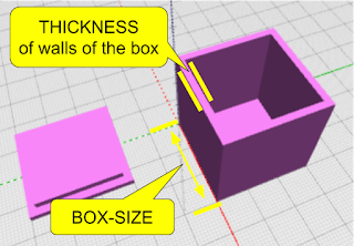
To achieve this, we will build a program using the coding blocks which use variables that can easily be changed to adjust all the aspects of the model which are dependent on them.

Writing the Code to Make The Box

First - let's plan out how to make a hollow box. The way this is often done in 3D Modeling is to create a cube which is the size of the outer dimensions of the box you want - and then create a smaller cube which can be "subtracted" from the inside of that first cube to hollow it out.
Great - and EASY!

We first decide what our Variables are. We pretty much already actually did that above - so let's just call them: box-size and thickness.  Then we'll use those in modeling the cubes we need.

> From the "VARIABLEs" category, drag over a "SET ITEM TO" block and create a "new variable" (in the drop down next to "Item") - and call the first one "block-size" - then do another variable called "thickness".

> From the MATH category, drag over a "0" number block and drop it into the "SET block-size TO" block - and change the value to 30 (we're starting with a 30mm box). Do the same with "thickness", but change that value to "2" (we're starting with 2mm wall thickness).

> Drag a "CUBE" block over.

> From the VARIABLES area, drag over the "block-size" block - which gives the VALUE of that block-size variable - and put it in the "X" component of the CUBE block. Then do the same again for "Y" and "Z". All of the 3 dimensions will be the same - 30mm.

At this point, you can test this program by just clicking the RENDER button. You should see a 30mm x 30mm x 30mm block appear in the rendered model window!

Making the Box Hollow


There are a set of very important coding blocks in a category called "SET OPS" (Set Operations) which let you do things like merge two shapes, or take the difference between two shapes. The "DIFFERENCE" block is the one we'll need here to hollow out the box - taking the difference between our original box and a slightly smaller box. If you're familiar with TinkerCAD, you know this as the "Hole" method. In Autodesk 123D Design, it is the "Combine" / "Subtract" feature.

First - let's make the smaller box. The measurement of this smaller box will basically be the size of the larger box (block-size) minus two times the thickness of the walls (once for each side). So the 30mm original box, needs a smaller box which is 30 - (2 x 2) or 26mm on the X and Y dimension - and 30 - 2 on the Z (height) dimension, so that the top of the box actually is open (we don't after all want a hollow box with no openings - we want the top to be open!)

Let's do the coding blocks now - using a new variable, some math and some transformations...

> from the VARIABLES category, create a new variable called sm-block.
This is the finished correct code for the Hollow Box.

> from the MATH catogory, take a math block which does ADDITION - then use the dropdown arrow to change that to SUBTRACTION. Take another of those same blocks again and make the second one MULTIPLICATION.

> Put the values in the blocks as shown to become the equation we described above (block-size - (2 x thickness)) and put that into the SET sm-block TO block.

> From the 3D Shapes category, take a CUBE block and set all the dimensions to the value of the "sm-block" variable.

OOPS! the smaller box was not centered
> From the SET OPS category, take a DIFFERENCE block and drag your original CUBE into the top slot, and the smaller cube into the bottom slot.

Now hit RENDER to test! OOPS! The two boxes clearly were not aligned! So the result of the subtraction did not turn out as planned.  To fix that, we'll move the smaller box to center it on the larger box - moving it by one wall thickness measurement on the x, y and z axis.

> from the TRANSFORM category, grab a TRANSLATE (move) block and set all the paarmeters to the value of the "thickness" variable.
> Put the smaller CUBE block inside that TRANSLATE block.
> Move the TRANSLATE block into the second slot of the DIFFERENCE block.
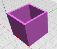
NOW test again... and BAM! You should see your hollow box.


This is Where The Magic Happens


Now - let's change the size of the box - while keeping the thickness of the walls at 2mm.
Pay attention or you'll miss it....
>  Change the value in the "Set block-size to" block to 50mm
>  Click the RENDER button.

You should now see a larger box! Play around - this helps to test your code and, assuming it works, gives you some satisfaction! Change the value of "thickness" (to 4 or 6) and click render. Those are some thick walls! Good thing you aren't stuck with that :)

In the next lesson, we'll make the Box Top - something that uses mostly the dimensions of the box but with a slight adjustment to allow for a perfect fitting top.


NOTE: this is the second in a 3-part series on making models with BlocksCAD code.
Part-1 - Making 3D Models with Code Blocks (aka Intro to BlocksCAD)

Mar 15, 2016

BlocksCAD 101 - Making 3D Models with Code Blocks

Most people say there are two ways to create digital 3D Models - 1) manually, using CAD (Computer Aided Design) and 3D Modeling software/apps - and 2) by scanning real-world objects with a camera or other scanning equipment to automatically interpret them into 3D Models.

But there's a third way to create 3D Models - you can CODE them.

Coding to create 3D Models


You can write a program which gives the computer commands which creates 3D objects. If you're a programmer, you can try something called OpenSCAD - which is basically a programming language which defines 3D objects. If you're not yet a programmer, and want to (or are willing to) learn some programming basics that pretty much anyone can learn, you can try BlocksCAD.

Overview of BlocksCAD


BlocksCAD is a block programming tool - similar to those used to teach coding to kids - which has commands and tools to create 3D Objects and is super easy to learn for kids or adults. It is available on the web, through your browser, so no programs to download and it is very friendly for Chromebooks.

BlocksCAD was developed by the Massachusetts-based Einsteins Workshop - a learning organization for kids. It combines aspects of doing simple programming (aka coding) with aspects of simple 3D Modeling. The results of BlocksCAD code are 3D Models which can be downloaded in .STL format for 3D Printing or for use in other programs which import .STL files (almost all do).

BlocksCAD interface - 3 main parts

Get Started in BlocksCAD


The BlocksCAD interface consists of 3 main parts:
1 - Library of available blocks
2 - YOUR blocks (that's your code)
3 - 3D Model Viewer

The process of creation is quite simple:

> Find the blocks you need from the Library of available blocks. Each category on the left side expands out to reveal all the blocks available in that category.

Sample flow - choosing the SPHERE block, and rendering it.
> Drag the block you need into your code area. Later you'll see how they snap together to form groups of commands - for now start simple.

> Adjust the values used in the blocks as needed. Each block has it's own options relevant to that command - for example - the Sphere block asks for the radius of the sphere.

> Click "Render" in the 3D Model Viewer to see the results!

Creating your first Coded 3D Model


Let's keep this really simple to start. Let's create a rectangle. Pay attention - this is so quick you might miss it....
> Click on the "3D Shapes" category on the left side.

> Grab the "CUBE" block and drag it to the main screen area (in the center).
> Click "RENDER" on the viewer window.

> DONE. You just coded your first 3D Model!

Notice that the CUBE block has 3 values and one option. The X, Y and Z values define the size of each of those dimensions. You can click on those and change them. Click RENDER after each change to see what they do. The "Not Centered" option could have been changed to "Centered" to put the model in the middle of all axis.

Using a Variable to Modify Your Shape


Now let's use a "variable" - a placeholder which has a value - to help define the dimensions of your shape. In this case, we'll define the X-Dimension of your cube (actually, rectangle).

> Go to the "VARIABLE" category
> Drag the "Set Item To" block into your blocks space and connect it to the top of the CUBE block. It should snap into place.
> Let's name the variable better to make it something more relevant. Use the dropdown on "Item" in the block to select "New Variable" and name it "xSize". This will represent the value in millimeters of the X-dimension of the cube.
> Go to the "MATH" category and drag the "0" value block (the tiny blue one on the top) into the empty space in that "Set xSize To" block.
> Change the value in the "0" block to "5" for now.
> In the VARIABLE category again, drag out the "xSize" block - which represents now the value stored in the variable you named "xSize".
> Drop that "xSize" value block into the cube block where the "X" value is shown (there's a "10" there now). Dropping this block will push the other block out of there. you can click that "10" block once and then hit the "delete" key on your keyboard to delete it.

You now have a simple way to model a cube with any X dimension simply by changing the value of the xSize variable. Not super useful yet - but later you will see why using variable gives you power to easily make adjustable models for customization without re-drawing models.

Advantages of Coding 3D Models


The hollow box example you will learn in the next post
The idea behind coding 3D Models is to give an automated way to create custom objects. While plenty of 3D Models are actually artistic and benefit from human creativity, some models are simply functional and can be more quickly created using rules and precise measurements. That's where coding helps.

Let's take scaling for example (making a model larger or smaller)...
Most 3D Modeling apps and even Slicer apps make it easy to scale a 3D model to get larger or smaller sizes. But, sometimes, simple scaling can not achieve the desired outcome. For example, if you have a simple, square, hollow, open-top box which is 20mm square with walls which are 2mm thick. If you want a 40mm box, you can easily scale the model to 200% before printing. But then the walls of the new box will be twice as thick - 4mm instead of 2mm. That is not likely what you wanted. Most modeling apps even let you constrain the scaling to X, Y or Z axis - but in this example, there is no way to avoid the change to the wall thickness.

With Coding, I could easily separate the thickness of the walls of this box to be it's own setting (it's own VARIABLE!). This, in fact is the exact example which we will review in the next post - so stick around! In the next lesson, we'll learn how to make a 3D Hollow Box that Grows!

NOTE: this is the first in a 4-part series on making models with BlocksCAD code.
Part-1 - Making 3D Models with Code Blocks (aka Intro to BlocksCAD)
Part 2 - BlocksCAD 102 - Coding a #3D Box that Grows


Mar 12, 2016

An Improved 3D Printed CodeBug Case


My first attempt at the CodeBug case was mostly meant to look good - but it clearly had one significant drawback; it blocked direct access to the conductive "Legs" on the sides.

For more permanent project installations, the first version would allow soldered wire access just fine, but many of the learning projects on the CodeBug site use alligator clips - so I wanted to make room for that in this adjusted design.

Design adjustments


The fully stripped down starting point. Look ma, no feet.
In some ways, this new version should have been the first version - since it is actually simpler. I started by stripping it down to the basics - simply removing the side panels on the case and trimming the cover to match. I also removed the goofy feet and the robot arm connectors.

Without the sides, all the legs stick out with enough room for an alligator clip on each - but I now wanted to add back a little personality.

Since those side panels is where I had the robot-connector arms - purely for custom looking designs - I just moved those to the bottom and - since I had removed the goofy feet-shaped feet - now I can design custom feet or arms or other appendages to make the CodeBug gain some personality.

I also added a robot arm connector to the top middle, under the wire port, to allow for more aesthetic adjustments later.


The Model


Look for this one soon online - still have some adjustments to make...


Mar 4, 2016

3D Printed 4-Leaf Clover Bookmark for St. Patricks day

After the Valentines Day Heart paperclip, the Football paperclip, the "We Hate Paper" paperclip and the Creeper Clip - I was sure the paperclip... errr... BOOKMARK phenomenon was over. But then. This.

So, first of all - they're not 3D Printed paperclips. They're 3D Printed bookmarks. 

That is so much less offensive, since everyone knows We Hate Paper. Second, Saint Patrick's Day had to be celebrated with something 3D Printed - so what better, easier way to do that than with a Bookmark? (you thought I was going to say paperclip)

Design Goals


Let's face it. I had one goal here. Simple, Fast and Cute. Oh - I mean I had 3 goals here.

Design Summary


Saint Patrick's Day has a few iconic symbols, but I think the 4-leaf clover is the only non-controversial one (I mean, I don't really even know what a Leprechaun is, and I refuse to drink green beer). So - starting with the Heart-shaped paperclip (Bookmark!), I simply transformed it using very similar dimensions.


Design Challenge


There was one very tricky part to this design. While each leaf of the clover leaf looks like a simple heart, it definitely has a distinct inward curve down the center of each leaf. It was quite hard to achieve that in a clover shape. When I used the basic heart from the Valentines Heart model, it just didn't look like a clover leaf. So I tried something else...


I basically took an elongated and flattened oval-shaped sphere (is there a name for an oval-shaped sphere?) and then cookie-cut a half heart shape out of it to make each half of each leaf of the clover. Then put those pairs together for each leaf. Then duplicated that to make four leaves. The stem was simply a curved spline extruded and rounded - and the outer clip part is a cylinder with the middle cut out.

The Model


You can get the Clover Bookmark here (don't you dare use it as a paperclip!)... and I strongly recommend printing a few hundred of these and giving them to your friends before they celebrate Saint Patrick's day!

If your friends don't like Bookmarks, you can always give them Free Donuts.


Mar 1, 2016

The real payoff of 3D Printing: Free Donuts

I've got a new side project - one that's not really in full motion yet - in fact it is hardly started - but it still needed a mascot, an icon, a persona. Isn't that the most fun part of any project, naming it and giving it personality? Yes, of course it is.

Well, for this one, we decided the personality would be a Donut - yes, with a capital D. And please accept this simpler spelling rather than the annoying and all-too-accurate Doughnut spelling.

As with any good product, it's a loser without a 3D Printed product logo - so - the quest to 3D Model and 3D Print a frosted, sprinkled, delicious Donut began.

Design Goals


What I wanted most out of this model was for the final product to actually look like a donut - unmistakably. 

For man made objects which have structure - like buildings or cars or, uh, Raspberry Pi cases, it is pretty easy to represent the object in 3D modeling. 

But for things which occur naturally in our environment - like a Donut - it's a bit harder. I wanted to capture the Donut in it's natural state - soft, sugary, harmful, yet delicious. 

Are you hungry yet?

The type of Donut I selected to model was also critical. I choose a broadly accepted favorite - the Chocolate Frosted Sprinkled Donut - knowing that done right, it would be impossible to deny.

Design Start


Let's face it - without the frosting, the Donut project would be a simple Torus - the rounded and circular shape often called a... Donut. The hard part was the frosting. I literally stared at a picture of donut for 7 hours straight (well... maybe it was 7 minutes, but you get the idea) before figuring out a strategy to achieve frosting which had both a rounded top to match the contour of the Donut and drippy sides to represent that perfectly desirable, about-to-melt look. 

First, I drew a splatter shape with the Spline tool (just random curves connected at the end into a circle. Then I drew another similar shape - smaller and inside the first - for the inside part that would fit against the Donut hole. I extruded the space between the two shapes into a donut-like splatter shape - 4mm high.

The main issue now was to give it a curve to match and sit atop the donut.

Now, I duplicated the donut and sat the splatter shape on top of it - sinking it almost all the way down into the top of the donut. I then sized the splatter so that the ends barely touched the outer part of the donut.

Donut Design Magic


The magic was about to happen. 

I used the "Combine" / "Intersect" tool - with a copy of the Donut as the source - and the splatter as the target - to get a perfectly contoured splatter shape which could be fit on top of the donut! I simply enlarged it slightly and raised it to sit on top of the Donut.

The sprinkles were easy-ish - they are each just small cylinders (approx 2-3mm long and 1mm diameter) with rounded ends. I placed each individually atop, and slightly sunken into, the chocolate frosting.  I also gave each a slightly random tilt and turn - giving that "dropped onto the frosting in a carefree manner" look. (I've lost you, haven't I)

Additional Details


To make the Donut lay better on the printer bed, I added a 3mm wide flat cylinder to the bottom aligned perfectly to the tangent points that were touching the bed. Of course, I also added a key ring loop so the Donut could be conveniently displayed to make all around you jealous.

Some resizing steps were taken - harder that I had hoped - to make the Donut small enough to print fast, but big enough to notice the detail. And - as I have done before - I used Sharpies (tm) to color the donut quickly.

The model


The MkrClub Delicious Donut model can be found here - where it will attract the most hungry, sweet-toothed 3D Print enthusiasts.

Feb 28, 2016

Google Calendar 3D Printed Logo


It has been quite a while since I've modeled a Google product icon (Expeditions), and much longer since I did my first (Google Docs!) - so I thought it was time to catch up with some others that are deserving. Google Calendar is one of my most used products, so here it is.

Design Goals


The Google Calendar icon is unique in that it attempts to represent a perspective look - that is a 3Dimensional look - in a 2D design. So with this one, I wanted to try to achieve the look of the icon with an actual 3D model. You can see the result of the 3D Model - viewed at the right perspective - looks pretty well like the 2D version.


Design Process


Revolve tool created perspective
To get the dimensions right, I used the Google Drawings trick - where I trace the image. I could have easily just measured the dimensions - since the foundation of this design is just a few rectangles.

In the end, I had three rectangles - One for the base (which has the two holes at the top), one for the top part of the calendar numbers and one for the lower part. Both of those calendar parts sit on top of the base.

To get the perspective angles on the top and bottom of the rectangles, I used the "revolve" extrusion tool in Autodesk 123D Design. The bottom part, I revolved 15 degrees, and the top part, 30 degrees. Then I used the "Filet" tool to round the corners.

To get the numbers embossed into the two halves, I actually created the numbers using the "Text" tool, and then cut the numbers in half. Then I aligned each half to be flush with the top surface of each of the respective calendar halves and pushed them into the surface by 2mm. Then, of course, I "Subtract"ed them from each half - and voila! I had the look of a real paper flipping calendar!

The Model


Since this is one of the Google Product icons, I've added it to my Product Icons page, which you can find right here on my blog (the tab at the top takes you there) along with many other product icons.