Showing posts with label maker. Show all posts

Oct 9, 2018

Laser Cut Project #1 on Glowforge: a Custom Phone Stand (of course)

Within hours of getting my Glowforge laser printer set up (they call it a printer - it's really a cutter), I had to design and print/cut something of my own. Of course I did cut one of the free designs on the Glowforge web site - the classic snap-together box - but everyone who knows me knows it's the design process that makes me happy, not just printing pre-made designs.

What better first object to design than a custom phone stand?! I've never done that before (ahem).

The design I had in my mind was quite simple, so I sketched a quick version of the idea on paper - it was just two identical, vertical parts which actually support the phone, and a perpendicular support which keeps the two stand parts aligned and stable.

Detailed Requirements Planning


I barely needed any more planning - but, as in all product design, it's good practice to think about what I'm trying to achieve in more detail. I like to think about all my projects like this: What am I trying to achieve with this product? What problems should it solve?

What are my "Design Do's and Don'ts" for this product? 
Here's the simple list I compiled for this phone stand product:

  1. Hold a phone easily and quickly without having to open, close, snap-in, pry or otherwise fit the phone into anything. I just want to drop it in and easily take it out.
  2. Hold a phone BOTH vertically (portrait) AND horizontally (landscape).
  3. Hold a phone at a comfortable video-viewing angle on the desk - mostly upright, not flat - less than 90 degrees from the desk, but more than 45.
  4. Hold any phone, regardless of size, including my big Pixel XL and my son's small iPhone.
  5. Don't obstruct any of the screen.
  6. Be easy and fast to cut on the Laser Cutter, using minimal materials. Cheap to make.
  7. Be simple, not fancy - since it's mostly hidden behind the phone.
  8. Easy to put together, and bonus if it comes apart to fit in your pocket.

Reflecting on the Design Process


Even for a project this simple, you can see it's pretty easy to quickly come up with a whole lot of detailed requirements! That's actually what we do at work all day as product managers - mostly with software - but sometimes with hardware. I think it's good practice to be this detailed and diligent with #maker projects too, especially when it's teachers using these projects as lessons to achieve other learning objectives.

This allows for each requirement to explicitly be solved with math or art and design or other skills, depending on the project. Every one of these requirements can have it's own failures, learnings, solutions, inventions and insights attached to it - and this is where even a simple project becomes an engaging and inspiring learning adventure!

Cardboard Prototype


I did a rough sketch using a fantastic, free iPad app called "Vectornator Pro", which makes it really simple to create a multi-point vector design that can be adjusted by simply moving the points or changing the curves. When I had the 3-parts roughly designed, I moved right into laser-cutting, and cut it out of cardboard first to see how far off I might be. Surprisingly, the design mostly worked on the first try! There were small tweaks I could make to hold larger devices, maybe allow for a couple of different angles with the same device - but generally, the design met most of my requirements!


The cardboard version was actually strong enough to hold my phone firmly - maybe I should stop here and declare victory ;).  I quickly realized this design could be used to hold other things too - like business cards - so even my cardboard prototypes are being put to good use as business card holders.

Getting to a Final Version


The next step was cutting this design out of "real" material - something that will hold up to being used everyday, like wood or acrylic. It became clear with the first print that the design needed two tweaks.

First, I wanted the three parts to stay firmly together so it didn't fall apart when picked up, but be able to come apart when needed (for pocket carrying). I experimented with notch designs which help the parts "click-in" and stay together, but are simple to pull apart. (Note: this was a revisit design adjustment once I had more experience with the Laser Cutter and acrylic material... not a beginner design.)

Second, I wanted it to feel firm and not flimsy - which wasn't true of this current design. The 3-part design felt like it could break easily - it was "racking" (a wood-working term where an object doesn't have the right opposing angles of support, making it prone to leaning or breakage at the joints). It was simple and it worked... but I wanted it to be better.

Iterate!


I decided that I could provide TWO angles for the phone to rest by adding a second set of holders to the otherwise useless back-side of the stand - this worked pretty well and with a little adjustment in the depth of the base - to avoid the phone from tipping over with that shallower angle.

Calling it Done


I decided to add a 4th part - another support which would help keep the two vertical stands aligned and not prone to motion which could break it. This, of course led me to many experiments - and I quickly violated one of my own design "Don'ts" - I started thinking about the aesthetics. Even though I came up with a very strong design with a 4th part, I didn't like the aesthetic. I proceeded to spend too much time trying to make it look better - and ended up with two final designs - one stronger, one prettier.  These became the final versions... for now... since no design is ever actually "done" ;)

Mar 15, 2017

BlocksCAD 104: 3D Modeling a Multi-compartment Box with Code


BlocksCAD combines two of my favorite things: Coding and 3D Modeling. I've written about BlocksCAD before - to show the basics of how code can be used to produce 3D Models - and more recently I found a real world use for this tool that I just had to share.
Note: This is basically the 4th in a series of posts about modeling with BlocksCAD. The first is here.

Background


A while back I created a small "Battery Holder Box" - which was specifically designed to hold one type of button battery - the CR2032. This small battery has specific dimensions, so my 3D Model was made to fit that specific battery. I made a single model with specially sized compartments to hold 10 of these batteries.

About a week later, I needed another similar box to hold LR44 batteries, which are slightly different dimensions than the first - so I went through the painstaking process of reproducing the battery box to those dimensions.

Then a few weeks after that, I wanted a similar box to hold SD cards - and again, I grimaced while I considered repeating all the steps to create a specially sized box to hold a dozen SD cards. Then it struck me - I can CODE THIS!

The Power of BlocksCAD
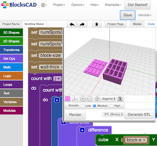

As a software engineer, I'm trained to recognize patterns like this - and it's exciting when a pattern as obvious as the above can be turned into code. That's what BlocksCAD lets me do! Using code to produce storage boxes like this, I can use parameters (variables) to change the measurements in my code, and within seconds, have practically ANY size compartment and box configuration!

How I Made AnyBox - an overview


I'm going to give you just the basics here - I won't describe every line of code (or, in this case block of code).

I start by creating ONE compartment. It's basically a hollowed out rectangle meant to hold something - a box. From there, I simply make a bunch of those compartments by repeating the same code as many times as necessary. I do this in two dimensions - so I can have, for example, 3 across and 4 down, or 1 across and 3 down - similar to what a book case might look like. Once the boxes are done, I create a TOP - with the exact configuration of n across and m down as the boxes, but with a more flat extrusion vertically.

That's the high level story - below is the detail...

Making the First Box


I start by creating ONE box, one compartment - using 3 variables - the width (X), the length (Y) and the height (Z). These measurements are the measurements of the INSIDE of the compartment that I wanted. So I basically measure the dimensions of the object I'm trying to hold in the box, and use those for X, Y and Z.

The "CUBE" block in BlocksCAD easily produces the cube with those dimensions. But I don't actually want a solid cube, I want a hollow cube.  To achieve a hollow cube, I have to use the TRANSFORM / MINUS block to subtract this cube from a slightly larger cube.

To decide how much larger that outer cube should be, I have another variable which holds the "Wall Thickness" (let's call that W here) of the box I want - and I add that to the original X, Y and Z dimensions to get the outer cube dimensions. Now the outer box can be defined as X+W, Y+W, Z+W.

Watch The Box Multiply


Now that I have ONE compartment successfully made, I can repeat the creation to make an array of boxes connected to each other to get the "cubby" look I'm aiming for. Remember the original reason for this was to hold several of the same item - button batteries in my case.

One of the great things about programming is that once you figure out how to do something, you can re-use the code to do it again. So in this case, now that I know how to make a box in the dimensions I want, I can just repeat the code to do it again. All I have to do is start the second box just next to the first, and then again, start the third box, just next to the second, etc.
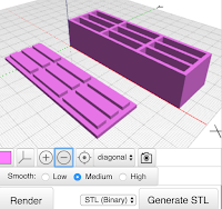
I do this with a LOOP (in coding, it is also called "iteration") to simply repeat the running of that box-creation code over and over again, as many times as the number of boxes I want. Since I want the option to have multi-dimensional cubbies - I also need a second loop around that first loop to repeat that whole set of boxes again, making another set of n boxes next to the first set of n boxes.

This is a very common pattern in coding whenever you are dealing with any sort of array - in this case it happens to be the physical creation of a multi-dimensional array object.

Making The Box Top
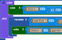


Before worrying about the complicated box top needed to cover this multi-box configuration I've now created, I need to make a TOP for that ONE compartment first. To do this, I'll use the same X, Y measurements from earlier - but I really don't need the Z, as the top will be mostly a flat top with minimal depth.

I start by creating a simple rectangle which is the same dimensions as the outer dimensions of the box - that is X+W by Y+W - which accounts for the width of the box walls again. Now, instead of hollowing out, like we did for the box, this time we want to create a slightly raised, slightly smaller panel which fits snugly inside the top of the box to hold the top on. This is done by creating another rectangle on top of the first which does NOT include the wall thickness, but just the inside dimensions X and Y.
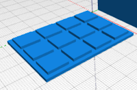
Now that we have one box compartment, we simply do the same thing we did with the box, and use a double loop to create the same number of tops connected to each other as we the box had.

Practical Addition From Testing


Along the way, of course I tested the creation of the single box, then multiple boxes in one row, then multiple boxes in an array of 2 x 3 and larger. The box was working quite well! But once I actually put objects in the box, button batteries in my case, I found a slight problem. There was no great way to get the objects OUT of the box! I had to turn over the box to get one object out, which of course dumped all the objects out.
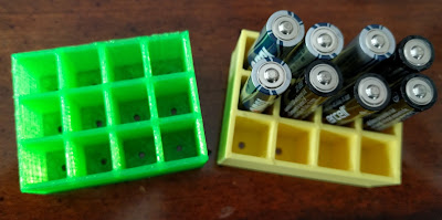
To solve this, I added one small feature - or should I say, I subtracted something. I created a small circular hole at the bottom of each compartment  (by subtracting a centered cylinder from the base of each box) - which can be used to push objects out of their compartment when needed (using a paperclip or other small pointy object). This worked just fine!

The Missing Steps Have The Real Learning


Like with all great projects, the description above doesn't really tell the whole story. There are many details left out. I don't do this to torture you, but rather because I can't remember all the smaller tweaks and adjustments I had to make to make this project work - AND, because that is where all the learning is! If I gave you every detail, you'd learn much less than if you had to figure out some of the stuff yourself.

Chances are, in doing this project yourself, you'll discover a completely new way to do this project or perhaps invent some other cool object I didn't think about!

NOTE: this is the FOURTH in a 4-part series on making models with BlocksCAD code.
Part-1 - Making 3D Models with Code Blocks (aka Intro to BlocksCAD)
Part 2 - BlocksCAD 102 - Coding a #3D Box that Grows

Apr 12, 2016

5 reasons to have a 3D Printing Pen

My first 3D Pen - 3Doodler 1.0
More than a year ago, I saw my first 3D Pen - the 3Doodler - and I immediately bought it. It seemed like such a cool combination of creativity and modern technology. I had already gotten into "traditional 3D Printing" (did I really just say "traditional"?), and figured this was a natural extension of that. I didn't have any expectations of how or why I would use it, but bought it to help figure that out.

Why have a 3D Pen?


After using my 3D pen a few times, I really enjoyed creating things with it, but I also recognized that there are reasons to have them that differ a bit from the reasons for having a 3D Printer. That's what I'll outline here, a few reasons why a 3D Pen might be something you "need"...

Reason 1: Help you understand 3D Printing.

While 3D Printing is not rocket surgery, it's more fun to learn how it works by seeing it rather than reading about it or watching a video. A 3D Pen is a low cost, simple way to see 3D Printing mechanics in action. Yes, it's just plastic melting and being re-formed to harden again. But seeing it first hand - and being able to quickly create something without 3D Modeling skills or expensive machines - is cool.

Reason 2: Be Artistic in a New Way

My 2nd one - the Scribbler 3D Pen
Kids - and bigger people - often love making things. Crayons, markers, paint, yarn and fabric, even duct tape - it's all fun. But how often is there a NEW medium to create things? Not often. Melting plastic and reforming it into a new thing - now that's NEW - that's COOL.

Reason 3: It's Easy.

Making 3D objects with wood is amazing, but very hard, requiring many tools, perhaps dangerous electrical tools, and very time consuming.  Paper machè is great and simple - but it's messy! 3D Pens are easy to set up, take almost no time to get going, have minimal training with very small danger risks (watch the hot end!) and super easy to clean up. Learning how to do it is easy too! In a short session, kids can see results and even collaborate by building different parts of a larger model.

Reason 4: It's Cheap(er).

A great 3D Pen costs about $100 (although I actually got my Scribbler 3D Pen for $69, even though they now seem to be no less than $99). The PLA filament is also very cheap - about $20 for a whole roll (and you can try to calculate how much a printed object costs). A good 3D Printer costs about $500-$1000, and a better one costs more like $2000.

some experimental creations ("art")

Reason 5: Practice Experimenting and Failure

If you think creating something with a pen or crayon that you would call "Art" is difficult, well, just imagine trying that in three dimensions ;)

One thing I love about all arts and crafts is the practice it gives us - as kids and adults - in trying new things, in experimenting, in failing and trying again! Experimenting is such an important step in innovating, and that's why I love all kinds of art for EVERYONE. The 3D Pen is a great tool for this sort of practice - and is a fun alternative that spurs people's interest in something they may have never tried before. That's a good thing!

One reason to NOT get a 3D Pen.


Do not get a 3D Pen as an alternative to a 3D Printer.

not so precise mini-building
It is not at all the same thing. A 3D Printer is basically a robot which melts plastic and forms it into an object that has been modeled with 3D Modeling software. While that type of 3D PRINTING is not artistic - the 3D Modeling part can be VERY artistic. It's just that the actual printing process is not the artistic part when using a 3D Printer.

Conversely, the 3D Pen is NOT a good way to precisely create a 3D object for functional use. It is very hard to create an object of precise measurements or with straight edges or smooth, measured curves.

The comparison of 3D Pens to 3D Printers is analogous to comparing drawing by hand to printing with an inkjet printer - the first being artistic, the second being functional. Bat, as in 3D Printing, an inkjet printer required perhaps some artistic process first, before the actual printing step.

Here's what you'll have a lot of...
One other important point:  Because using the 3D Pen means having it closer to your face while you use it, you should ONLY use PLA - NOT ABS. It has been found that ABS Plastic often has harmful fumes, while most PLA does not.

Engadget wrote a post on this recently, which I try to share with everyone I know who does 3D Printing under any conditions - but I think it is even more important for 3D Pen use because of the likelihood of breathing in fumes.


Apr 10, 2016

Expanding Creativity With A 3D Printing Pen

3D Pens have popped up everywhere. Ok, not everywhere - like there are none in my sock drawer - but certainly in stores and online where, just a year ago, you would not have seen them.

If you have already tried a 3D Pen or bought one or generally know about them, you can stop reading now. If you wanted to understand the basics of what they are, this short post should help you.

What is a 3D Pen?


A 3D Pen is an electric tool which lets you create things out of plastic. It's a creative tool - perhaps it could even be called a toy. It is what I would call a modern version of play-dough.

Most 3D Pens take a strip of plastic "filament" into one side, heats it up to around 175 degrees Celsius (347 Fahrenheit!) and forces it out of the other side (tip) of the "pen" in a narrow stream allowing you to "draw" with it.

As the plastic dries, it hardens back into firm plastic, remaining in whatever form you created. If you've ever decorated a cake with one of those pastry bags, you pretty much know how to use a 3D Pen.

The plastic used is typically the same as that used by 3D Printers. PLA is the best option, as it has less harmful (or worrisome) fumes and melts at a slightly lower temperature (although, 345F is still pretty darn hot!). Some 3D Pens expect you to use their own "plastic sticks" - like the 3Doodler - but I prefer pens which are friendly to the same filament I'm using with my 3D Printer, so I don't have to buy separate material.

Scribber 3D Pen has a clear screen to show the settings

Controlling the 3D Pen


There are some basic controls on most 3D pens.

Temperature is the most important, as different plastic requires different temperatures.

Speed is another option on some pens, so you can control the rate at which the melted plastic comes out of the tip.

Then there's the motion - all pens which use plastic filament have both a forward (for drawing) and reverse (for removing un-used filament) - which allows you to "draw" or stop as you want to. That's pretty much it. Simple.

World's First, and My First - 3Doodler


The 3Doodler 1.0 - the original
The first 3D Pen I ever saw - in September 2014 at the MakerFaire in NYC - and apparently the first one ever invented, was the 3Doodler.

That first version of the 3Doodler, which I bought pretty much at first sight, was good - but not excellent - which is pretty expected given it was the "world's first". It was loud (it even has a fan in it) and bulky and had inconsistent reliability in my experience and clogged a couple of times too.

The 3Doodler 2.0 - from 3Doodler's site
That said, the first early 3Doodler helped me understand the concept well and frankly, amazed me.

Since then, the 3Doodler company greatly improved on their original design and now sells their second version which I don't own yet. IT has been considered by others to be a huge improvement over the first - Less bulky, quieter, more reliable.

I'll definitely try the version 2.0 3Doodler eventually, and I have the utmost respect for this company's founders, as they really innovated and broke new ground, defining this whole product category. You can now buy the 3Doodler in almost every innovative electronic-friendly toy or game shop and even in Brookstone and other high-end retailers.

3D Pens Galore


Scribbler 3D Pen
With 3Doodler's success in this new product category, it was inevitable that others would follow to create similar products. I've seen all sorts of variations on this theme now, but most are just basic knock-offs.

I decided to try one called the "Scribbler 3D Pen" (3rd generation). It was highly rated on Amazon and - at the time - was on sale for $69. (As of this writing, it is $99 in all the listings I could find).

I saw one completely new 3D Pen design at the NYC Toy Fair this past February called CreoPop - which uses liquid "ink" without heat - rather it uses LED lights to dry the ink as it emits from the pen's tip. This also seemed to allow more option in material with glow-in-the-dark, neon and more colors. This looked cool, but I haven't had a chance to try it first hand.

New 3D Pen version for kids coming


3Doodler Start and some creations
3Doodler is also showing and taking pre-orders for a completely new product called the 3Doodler Start.

This version operates at a much lower temperature with completely new filament which is non-toxic, making the whole kit much safer for younger kids!

I saw this product at the NYC Toy Fair in February 2016, and was VERY impressed. I expect this product to be a huge success for kids and schools if it proves to be reliable with reasonably priced filament. Nice to see 3Doodler continuing to innovate in 3D Pen Printing.

Conclusion


If you love crafts and Maker projects, and often have the opportunity to work with kids to encourage them to experiment and try new things - get a 3D Pen. Make no mistake - this tool is not for creating precision objects as you might do with a 3D Printer. This tool is mainly for creativity and art.

I haven't worked with enough different models to absolutely pick which is best and recommend a "winner" - but I will say that I've had great luck so far with the Scribbler 3D Pen myself and have heard good things about 3Doodlers 2.0 version.

Check ratings on Amazon and Google Shopping to get a broader opinion before buying.

Mar 12, 2016

An Improved 3D Printed CodeBug Case


My first attempt at the CodeBug case was mostly meant to look good - but it clearly had one significant drawback; it blocked direct access to the conductive "Legs" on the sides.

For more permanent project installations, the first version would allow soldered wire access just fine, but many of the learning projects on the CodeBug site use alligator clips - so I wanted to make room for that in this adjusted design.

Design adjustments


The fully stripped down starting point. Look ma, no feet.
In some ways, this new version should have been the first version - since it is actually simpler. I started by stripping it down to the basics - simply removing the side panels on the case and trimming the cover to match. I also removed the goofy feet and the robot arm connectors.

Without the sides, all the legs stick out with enough room for an alligator clip on each - but I now wanted to add back a little personality.

Since those side panels is where I had the robot-connector arms - purely for custom looking designs - I just moved those to the bottom and - since I had removed the goofy feet-shaped feet - now I can design custom feet or arms or other appendages to make the CodeBug gain some personality.

I also added a robot arm connector to the top middle, under the wire port, to allow for more aesthetic adjustments later.


The Model


Look for this one soon online - still have some adjustments to make...


Feb 12, 2016

CodeBug Gets a 3D Printed Box with Personality

If you've never seen CodeBug - let me introduce you.
CodeBug is "a cute, programmable and wearable device designed to introduce simple programming and electronic concepts to anyone". I first saw it at the BETT Educational Technology conference in London, where I met one of the founders, Tom Macpherson-Pope. As soon as I saw CodeBug, I new I must create a 3D Printed enclosure for it.

Design Goals


When I met CodeBug, I had just finished making my Raspberry Pi box, and brought some to the conference to show the Pi people. Now I had a similar target in the CodegBug - but what really excited me was the small size! I knew I could experiment and make variations without waiting 6 hours for the thing to print, as was the case with the Pi box.

What I really wanted in this first attempt, was just something that maintained some of the "cute" character of the CodeBug microprocessor board, but also made it easy to access the connectors (plugs and conductive "legs").

I also wanted the 5 x 5 led array to be exposed in a way which made it more fun to program - something like the mouth of a creature or a face of a robot or something similar.

Of course, I also wanted to have it stand up so it could be proudly displayed once it had a program loaded up.

Design Details


I decided that keeping with the original design meant that the buttons would be modeled to look like eyes and the 5 x 5 LED array to look like a mouth. While the CodeBug is called a bug, I saw more of a frog, so I called this first design the "CodeFrog".


I used a two-part design and gave it a clear shape to match the original board, but without every detail on each conductive leg. I also gave it clear eye-shaped sockets and gave it feet which both added to it's ability to stand up and helped to hold the two-part design together with the CodeBug board sandwiched in-between.

For design effect, I used parts of my prior 3D BitBot robot design to add a flexible arm - using the sockets attached to the body and then just using previously printed arms and hands to make it look cool.

Design Process


The most important thing was to make sure the face plate fit over the 5 x 5 LED array and the protruding buttons really well so that there was little movement and a strong connection. I measured and experimented with probably 5 or 6 prints before getting that right.

The base was also important to have a strong fit, and while the CodeBug board doesn't have screw holes to match, there is a battery protrusion on the back that was critical to fit into the base. I again played with that design until getting it just right, starting with a simple square base, and eventually shaping the base to match the face plate once I had the general position of the battery receptacle right.

I added a slit in the top of the feet to accept the bottom of the face plate and added small nubs inside the eye sockets to allow the face plate to click in and lock into the base. I only needed slight adjustments to make the face plate, CodeBug board and base work as a snap-together set.

Design Results


While this is really just a first attempt, I'm overall very satisfied with the result! My measure, of course, is whether this design inspires kids to want to code things on CodeBug which make this 3D Printed CodeFrog come to life. So far, I've gotten great reactions from my own kids, and I'll post follow ups once we have some programs to show beyond my own "mouth which opens and closes" program ;)

The Model


Look back here soon for the model - as I'll post it as soon as I do a bit of clean up on it.


Jan 30, 2016

A 3D Printed Filament Spool and a Discovery

I purchased a bunch of PLA filament for my Lulzbot TAZ4 a while back (from Ultimachine.com), and didn't realize until it arrived that I had bought the "Coil" version, instead of "on spool". For the first few months, I rigged up some crazy hanging jig which let the PLA feed out of the bag it came in - looking very much like a intravenous rig used to administer drugs or fluids (analogy un-intended). While this worked, it was wonky and suboptimal.

I decided to use this as an opportunity to design a 3D Printed spool to hold this PLA. I'm sure I could have gone out and bout one, or used the few (actually, just one) spools I have already depleted. But, as we say here at MkrClub, "Any excuse to design something new".

Design Goals


My main goal, of course, was to have something that worked. That meant it had to allow the PLA to be wrapped at a diameter which was loose enough not to snap it, and hold the PLA in place. The spool also had to have the right capacity to hold a full coil of PLA - about 1 Kg - and it should be adequate for both 3mm and 1.75mm PLA.

A close second goal was that the spool should print easily and quickly. I did not want to use tons of plastic printing a spool, and did not expect to just copy the dimensions and design of the standard spool. I expected - as I do so often - to have a multi-part design here.

Design Summary


The core of this design was, well, the core of the spool. I experimented in modeling a bit, and decided to design a hub and spoke model which had very simple and lightweight spokes coming out from the center (the hub). I did not think I needed any "rim" around the outside of the spokes, and that seemed to work just fine.

The spokes were designed as a pair of opposing spokes as a single object - which allowed me to vary the number of spokes used if I varied the size of the core/hob (for larger spools). I started with 4 pairs of spokes per hub, evenly spaced at 90 degree intervals.

Design Challenge


The connection of the spokes to the hub was a design challenge. I considered making each individual poke a separate object, but realized that as pairs they might be easier to connect in a strong way to the hub.

After some experimentation, I came up with a design that not only held very firmly, but used the slight flexibility in the PLA to allow the spokes to be "opened up" to grab onto the hub. Printing these parts flat also allowed for a slight "barb" on the connecting part, which helped created a strong connection until the spokes were physically squeezed to open the barbed ends back up again.

Testing Designs Efficiently


As with many designs, there are small parts that need to be tweaked before they are perfect. When the overall model is large, I like to use a novel approach to testing the most risky parts of the design without printing the whole model. I make a copy of the model and I slice it up into parts - isolating the part I want to test and printing ONLY that part.

For this spool design, it was the connection between the hub and spokes that was most risky and needed testing. Before printing the whole model, I cut off most of the spool, leaving only a small part of the circumference including the connecting part, and printed just that.


You can see in this picture what the TEST PRINT looked like, and this let me reduce the test print time and material by about 80% - giving me more patience to test until the connection was just right.

A Semi-Failure With A Discovery


Generally, the print did not work for me for a few reasons. First, the core was too small for 3mm filament - requiring too tight of a radius. I also need to add an angled hole in the hub to hold the end of the filament firmly. These are easy problems to fix.

So, while I was happy with the design overall, I'm pretty sure that using pre-used spools will suffice. This is likely another "unnecessary creation" which we 3D printing folk often produce ;)

The bright side of this design was the discovery of a new way to connect 3D Printed parts - a goal I've continually pursued. The flexibility of thin PLA prints created a locking mechanism that I'm sure will come in handy in other designs, as it gave me the best balance I've ever achieved between ease of connection and a firm hold.


Jan 2, 2016

A Fancy 3D Printed Raspberry Pi Enclosure

The Raspberry Pi helps make learning about computers fun and accessible for many people - and has given the maker community a powerful computing platform in a tiny package. Actually - it's a small integrated circuit board without a  "package" - it doesn't always even come with a case.

When my daughter opened up her new Kano Raspberry Pi kit that she got as a gift, the "package" - the enclosure for the electronics - was one of the things that made the kit approachable and easy. Then, within hours of that insight, a good friend and blogger asked me if I had designed a Raspberry Pi enclosure for 3D Printing. My response was a fast "Not yet, but it's on the way".

Design Goals


I wanted my Raspberry Pi enclosure design to be more than just a box with holes for the wires. I wanted it to be good looking and inviting. I decided I would use the Raspberry Pi logo itself as the design for the box. Of course the box had to also be functional. The Pi had to fit in there easily and have a way to secure it and, of course, all the wire ports need to be accessible. Of course, like so many designs I do, I wanted it to be easily printable without supports - and I expected it to be two parts - a bottom to hold the board, and a fitted top, preferably one which held securely without screws.

Summary of This Design Journey


There were a few forks in this design road - so I figured I should just summarize them first so readers get a sense of how I ended up with the current design.

    1) I started with the Raspberry Pi version 1 Model B (Two USB ports) - which has a specific size and layout of interface ports - implying layout of the holes in the sides of the case. Then I realized (after I got the general sizing all correct and printed) that most people, including my daughter, now have the version 2 design. (more info on Pi Models)

    2) I moved to the Raspberry Pi 2 layout - using my daughter's Kano board as my basis for measurement. That got me designing in the right direction,  and I completed a box design with the right layout to fit that Pi 2 board. But it seemed boring.

    3) I added a Raspberry Pi Logo-shaped bottom to the box, then created a custom top which was also in the shape and design of the Raspberry Pi logo. This looked really good - and had plenty of challenge creating the fitted top.

    4) The shape of the Raspberry Pi logo was so nice, that I decided to make the whole box that shape - with adjustments to fit the board within it. I was finally satisfied after some adjustments to the top to make the Raspberry-ness really show, some strengthening of the walls, better fittings to make the top snap in place and addition of optional screw holes. 

    This is where I am with my current design, but I'll fill in the details now for those who want to know more.

    Basic Design Of The Box


    I started with a box - figuring I would add the design elements as shapes on top and bottom of the box to give the whole package the appearance of the Raspberry Pi logo. So the focus to start was the alignment of the wire holes and screw holes and the general fit of the IC board.

    After measuring the Pi board (approx 85mm x 56mm), I created a basic rectangle with those outer dimensions plus an additional 3mm extra space on all sides - that's 2mm walls with 1mm space on each side. The rectangle is now 91mm x 62mm - and I use the "Shell" command and define 2mm walls to get the hollowed out box where the Pi will fit.

    Useful Trick for Early Design Testing


    Drawing with all measurements
    The placement of the seven (7!) port holes was critical to the success of the design, and no amount of measurement makes for a fool proof design or print. So, when I thought I had the whole bottom box design ready to go, I didn't want to print the whole thing until I was sure I hadn't messed something up. So, I came up with a method for testing a smaller version of my print to test that the placement of screw holes and wire port holes was correct.

    It's worth mentioning that I created a Google Drawing which documented all the measurements in once place visually.
    bottom portion only as a test

    I only needed to test the bottom half inch of height - about 20% of the total printed object - to see if the mounting holes and wire port holes were positioned correctly. To isolate that portion of the object, I created a big rectangle which was slightly larger than the whole box and positioned it over a copy of the box,  specifically positioning it over the portion of the box I did NOT want to print.

    Then I did a "Combine" / "Subtract" to remove the whole top of the copy of the box. That left me with the bottom portion. I printed that - which took about 45 minutes rather than the 3 hours the whole box would have taken, checked that it worked out, made adjustments and repeated. Two tries and it was done.

    The subtraction shapes used to cut the wire ports and SD slot

    Making Wire and Port Holes


    I had to make 7 holes in the sides of this basic box. It seemed the best way to do this to allow for a few later adjustments would be to create and position 7 rectangles which would be used to subtract material from the box. Any later adjustments I made, even to the box itself, would allow me to re-subtract these same boxes, in their correct positions, from the adjusted box. This turned out to be an insightful move, as I made many box adjustments that otherwise would have been hard to maintain the holes if they were pre-made in the box itself. Once the boxes were positioned correctly, I did the "combine"/"subtract" command - with all 7 rectangles as the source - and voila, the box had 7 holes in it.

    Screw mounts added where needed

    Securing the Pi Board (screw holes)


    To offer a way to secure the Pi board to the case seemed easy enough - since the Pi 1 has two screw holes and the Pi 2 has 4. But now that I had all my port and wire holes positioned, I realized that I needed to lift the board up a bit from the bottom of the case to give room for screws. This was luckily easier than it may have been, given the method I used to subtract the holes from the box. I just lifted all the subtraction shapes up 3mm and re-subtracted them from the box. I then placed small 3mm high rectangles (about 5mm square each) in the areas where the screw holes were needed and carefully measured as many angles as possible to get the holes positioned relative to the box sides and to each other. I used 1.25mm Radius cylinders to subtract holes from those shapes and aligned them to sit on the bottom of the box. Theses would also serve to hold the Pi board away from the bottom of the case with enough room for the bottom-mounted SD card and the small soldering nubs that stick out the bottom.

    The Raspberry Shape - from Simple to Complex


    To get the Raspberry Pi logo turned into a 3D object, I used an old trick that I've written about a couple of times. I pulled an image of the logo into Google Drawings and traced over it with the Polyline tool to create the Scalable Vector Graphics version that my 3D Modeling software can understand. With some foresight, I actually traced the outline of the raspberry separately from the inner designs of the raspberry, so that I would have some flexibility with the final objects.

    I went through several iterations of using this design. As mentioned earlier, first I created a base with the outer shape - and this definitely made the plain old box look more interesting. Then I created the top with all the inner designs subtracted out. This was also a huge improvement to the plain old box.

    Ultimately, after printing a very successful box shaped container with a top and bottom raspberry shape, I decided that the whole box should be raspberry shaped. The start was easy. I created the box with the raspberry outline extruded to 27mm, then hollowed out using the "Shell" tool in 123D Design. I then moved over the original box and started combining shapes - removing walls where they overlapped in areas which would be in the way of the Pi board, and combining walls where more support was needed.

    Then, my original idea to save the subtraction shapes for the 7 side holes came in super handy. I moved them over, in their relative positions, to the raspberry shaped box, and subtracted them again. This worked wonderfully! The Pi Board screw holes were also moved in their original positions after adding another 1mm of height to the mounts to give the board more breathing room and the screw holes more depth.

    Securing the Removable Box Top


    Making the top snap into place in a way which did not require top screws was one of my design goals, and became the toughest part of this design. I experimented with a few methods before settling on opposing and offset half-round, 1mm deep rim pieces. I originally added too many of these sets of snap-together parts, and the fit was too tight - but with four of these sets, the fit was just right.

    Even with the snap-togetherness of the top, I decided to add screw holes and mounts for people who want an ultra-secure enclosure. This was easy-ish - using tall 6x6mm towers on the inside of the box, and subtracting 2.5mm diameter screw holes 15mm deep into them, and through the top at the same time (to get perfect alignment).

    The Final Model


    There were lots of last minute adjustments, and overall, if I'm really honest about how much time I spent creating this model, I would estimate 10 hours of work not including printing time. I really obsessed over the design of the top, the combination of etched designs and full-through holes, which are functional in a case for something that might heat up like the Pi.

    The final model is now available on PinShape. Please post pictures of your print on PinShape or on Twitter and include @MkrClub !