Showing posts with label custom 3D models. Show all posts

Oct 9, 2018

Laser Cut Project #1 on Glowforge: a Custom Phone Stand (of course)

Within hours of getting my Glowforge laser printer set up (they call it a printer - it's really a cutter), I had to design and print/cut something of my own. Of course I did cut one of the free designs on the Glowforge web site - the classic snap-together box - but everyone who knows me knows it's the design process that makes me happy, not just printing pre-made designs.

What better first object to design than a custom phone stand?! I've never done that before (ahem).

The design I had in my mind was quite simple, so I sketched a quick version of the idea on paper - it was just two identical, vertical parts which actually support the phone, and a perpendicular support which keeps the two stand parts aligned and stable.

Detailed Requirements Planning


I barely needed any more planning - but, as in all product design, it's good practice to think about what I'm trying to achieve in more detail. I like to think about all my projects like this: What am I trying to achieve with this product? What problems should it solve?

What are my "Design Do's and Don'ts" for this product? 
Here's the simple list I compiled for this phone stand product:

  1. Hold a phone easily and quickly without having to open, close, snap-in, pry or otherwise fit the phone into anything. I just want to drop it in and easily take it out.
  2. Hold a phone BOTH vertically (portrait) AND horizontally (landscape).
  3. Hold a phone at a comfortable video-viewing angle on the desk - mostly upright, not flat - less than 90 degrees from the desk, but more than 45.
  4. Hold any phone, regardless of size, including my big Pixel XL and my son's small iPhone.
  5. Don't obstruct any of the screen.
  6. Be easy and fast to cut on the Laser Cutter, using minimal materials. Cheap to make.
  7. Be simple, not fancy - since it's mostly hidden behind the phone.
  8. Easy to put together, and bonus if it comes apart to fit in your pocket.

Reflecting on the Design Process


Even for a project this simple, you can see it's pretty easy to quickly come up with a whole lot of detailed requirements! That's actually what we do at work all day as product managers - mostly with software - but sometimes with hardware. I think it's good practice to be this detailed and diligent with #maker projects too, especially when it's teachers using these projects as lessons to achieve other learning objectives.

This allows for each requirement to explicitly be solved with math or art and design or other skills, depending on the project. Every one of these requirements can have it's own failures, learnings, solutions, inventions and insights attached to it - and this is where even a simple project becomes an engaging and inspiring learning adventure!

Cardboard Prototype


I did a rough sketch using a fantastic, free iPad app called "Vectornator Pro", which makes it really simple to create a multi-point vector design that can be adjusted by simply moving the points or changing the curves. When I had the 3-parts roughly designed, I moved right into laser-cutting, and cut it out of cardboard first to see how far off I might be. Surprisingly, the design mostly worked on the first try! There were small tweaks I could make to hold larger devices, maybe allow for a couple of different angles with the same device - but generally, the design met most of my requirements!


The cardboard version was actually strong enough to hold my phone firmly - maybe I should stop here and declare victory ;).  I quickly realized this design could be used to hold other things too - like business cards - so even my cardboard prototypes are being put to good use as business card holders.

Getting to a Final Version


The next step was cutting this design out of "real" material - something that will hold up to being used everyday, like wood or acrylic. It became clear with the first print that the design needed two tweaks.

First, I wanted the three parts to stay firmly together so it didn't fall apart when picked up, but be able to come apart when needed (for pocket carrying). I experimented with notch designs which help the parts "click-in" and stay together, but are simple to pull apart. (Note: this was a revisit design adjustment once I had more experience with the Laser Cutter and acrylic material... not a beginner design.)

Second, I wanted it to feel firm and not flimsy - which wasn't true of this current design. The 3-part design felt like it could break easily - it was "racking" (a wood-working term where an object doesn't have the right opposing angles of support, making it prone to leaning or breakage at the joints). It was simple and it worked... but I wanted it to be better.

Iterate!


I decided that I could provide TWO angles for the phone to rest by adding a second set of holders to the otherwise useless back-side of the stand - this worked pretty well and with a little adjustment in the depth of the base - to avoid the phone from tipping over with that shallower angle.

Calling it Done


I decided to add a 4th part - another support which would help keep the two vertical stands aligned and not prone to motion which could break it. This, of course led me to many experiments - and I quickly violated one of my own design "Don'ts" - I started thinking about the aesthetics. Even though I came up with a very strong design with a 4th part, I didn't like the aesthetic. I proceeded to spend too much time trying to make it look better - and ended up with two final designs - one stronger, one prettier.  These became the final versions... for now... since no design is ever actually "done" ;)

Mar 15, 2017

BlocksCAD 104: 3D Modeling a Multi-compartment Box with Code


BlocksCAD combines two of my favorite things: Coding and 3D Modeling. I've written about BlocksCAD before - to show the basics of how code can be used to produce 3D Models - and more recently I found a real world use for this tool that I just had to share.
Note: This is basically the 4th in a series of posts about modeling with BlocksCAD. The first is here.

Background


A while back I created a small "Battery Holder Box" - which was specifically designed to hold one type of button battery - the CR2032. This small battery has specific dimensions, so my 3D Model was made to fit that specific battery. I made a single model with specially sized compartments to hold 10 of these batteries.

About a week later, I needed another similar box to hold LR44 batteries, which are slightly different dimensions than the first - so I went through the painstaking process of reproducing the battery box to those dimensions.

Then a few weeks after that, I wanted a similar box to hold SD cards - and again, I grimaced while I considered repeating all the steps to create a specially sized box to hold a dozen SD cards. Then it struck me - I can CODE THIS!

The Power of BlocksCAD
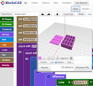

As a software engineer, I'm trained to recognize patterns like this - and it's exciting when a pattern as obvious as the above can be turned into code. That's what BlocksCAD lets me do! Using code to produce storage boxes like this, I can use parameters (variables) to change the measurements in my code, and within seconds, have practically ANY size compartment and box configuration!

How I Made AnyBox - an overview


I'm going to give you just the basics here - I won't describe every line of code (or, in this case block of code).

I start by creating ONE compartment. It's basically a hollowed out rectangle meant to hold something - a box. From there, I simply make a bunch of those compartments by repeating the same code as many times as necessary. I do this in two dimensions - so I can have, for example, 3 across and 4 down, or 1 across and 3 down - similar to what a book case might look like. Once the boxes are done, I create a TOP - with the exact configuration of n across and m down as the boxes, but with a more flat extrusion vertically.

That's the high level story - below is the detail...

Making the First Box


I start by creating ONE box, one compartment - using 3 variables - the width (X), the length (Y) and the height (Z). These measurements are the measurements of the INSIDE of the compartment that I wanted. So I basically measure the dimensions of the object I'm trying to hold in the box, and use those for X, Y and Z.

The "CUBE" block in BlocksCAD easily produces the cube with those dimensions. But I don't actually want a solid cube, I want a hollow cube.  To achieve a hollow cube, I have to use the TRANSFORM / MINUS block to subtract this cube from a slightly larger cube.

To decide how much larger that outer cube should be, I have another variable which holds the "Wall Thickness" (let's call that W here) of the box I want - and I add that to the original X, Y and Z dimensions to get the outer cube dimensions. Now the outer box can be defined as X+W, Y+W, Z+W.

Watch The Box Multiply


Now that I have ONE compartment successfully made, I can repeat the creation to make an array of boxes connected to each other to get the "cubby" look I'm aiming for. Remember the original reason for this was to hold several of the same item - button batteries in my case.

One of the great things about programming is that once you figure out how to do something, you can re-use the code to do it again. So in this case, now that I know how to make a box in the dimensions I want, I can just repeat the code to do it again. All I have to do is start the second box just next to the first, and then again, start the third box, just next to the second, etc.
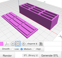
I do this with a LOOP (in coding, it is also called "iteration") to simply repeat the running of that box-creation code over and over again, as many times as the number of boxes I want. Since I want the option to have multi-dimensional cubbies - I also need a second loop around that first loop to repeat that whole set of boxes again, making another set of n boxes next to the first set of n boxes.

This is a very common pattern in coding whenever you are dealing with any sort of array - in this case it happens to be the physical creation of a multi-dimensional array object.

Making The Box Top
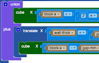


Before worrying about the complicated box top needed to cover this multi-box configuration I've now created, I need to make a TOP for that ONE compartment first. To do this, I'll use the same X, Y measurements from earlier - but I really don't need the Z, as the top will be mostly a flat top with minimal depth.

I start by creating a simple rectangle which is the same dimensions as the outer dimensions of the box - that is X+W by Y+W - which accounts for the width of the box walls again. Now, instead of hollowing out, like we did for the box, this time we want to create a slightly raised, slightly smaller panel which fits snugly inside the top of the box to hold the top on. This is done by creating another rectangle on top of the first which does NOT include the wall thickness, but just the inside dimensions X and Y.
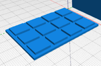
Now that we have one box compartment, we simply do the same thing we did with the box, and use a double loop to create the same number of tops connected to each other as we the box had.

Practical Addition From Testing


Along the way, of course I tested the creation of the single box, then multiple boxes in one row, then multiple boxes in an array of 2 x 3 and larger. The box was working quite well! But once I actually put objects in the box, button batteries in my case, I found a slight problem. There was no great way to get the objects OUT of the box! I had to turn over the box to get one object out, which of course dumped all the objects out.
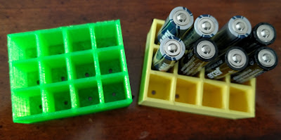
To solve this, I added one small feature - or should I say, I subtracted something. I created a small circular hole at the bottom of each compartment  (by subtracting a centered cylinder from the base of each box) - which can be used to push objects out of their compartment when needed (using a paperclip or other small pointy object). This worked just fine!

The Missing Steps Have The Real Learning


Like with all great projects, the description above doesn't really tell the whole story. There are many details left out. I don't do this to torture you, but rather because I can't remember all the smaller tweaks and adjustments I had to make to make this project work - AND, because that is where all the learning is! If I gave you every detail, you'd learn much less than if you had to figure out some of the stuff yourself.

Chances are, in doing this project yourself, you'll discover a completely new way to do this project or perhaps invent some other cool object I didn't think about!

NOTE: this is the FOURTH in a 4-part series on making models with BlocksCAD code.
Part-1 - Making 3D Models with Code Blocks (aka Intro to BlocksCAD)
Part 2 - BlocksCAD 102 - Coding a #3D Box that Grows

Jan 8, 2017

Yet Another 3D Printed Phone Stand

I got tired of laying my phone down next to my computer - so I wanted a simple phone stand that would stand my phone upright or sideways so I could see it and use it. Of course there are likely cheap phone stands or 3D Models that would suit my purpose somewhere - but I had two reasons why I "needed" to make my own:

First, I wanted it to suit my needs and fit my phone exactly.

Second, I like to make stuff - so why pass up the opportunity to invent something new!?

Design Requirements


The basic requirement of this design was to firmly hold my phone upright without tipping over. But there were other things I had to consider in this design. Here's the full list:
  • Hold phone upright (portrait) without tipping and with firmness that let me tap the screen.
  • Hold phone in sideways (landscape) too. (hopeful on this one)
  • Have a slight angle so it is easy to see on my desk.
  • Nothing should block ANY of the screen.
  • Simple & Fast to print - no supports, flat bottom surface to grip print bed, minimal mass.
  • Able to hold phones approximately the size of my Nexus 6P with or without a case.
Things I decided not to worry about for this first design included a way to dock the phone on the charging cable or making the stand portable to fit in my pocket. As with any product, sometimes it's just as important to pick things you're NOT trying to solve as it is to pick those problems you ARE trying to solve.

The 3D Model


This one was not as simple as it looks. The requirements I had to be simple and low mass made it more of a challenge - otherwise, I could have simply used a big block (as I've seen in many other phone holders).

I started with a block. I imagined the shape I wanted to be more like a wedge, holding the phone on the front, then angled back to the bottom surface.

To get the right shape of the front which would hold the phone, I created a 3D Model of my phone - not to be printed, but to be used as a shape to SUBTRACT from the wedge block to leave behind a perfectly shaped area to hold my phone. I then subtracted a large chunk of the block from the angled front for the area where the phone screen would be seen, leaving about 5mm on each side, about 3mm thick, to hold the phone in place by the edges.

Now, as with any subtraction operation like this, the fit would be too tight if I just printed it as is - so I pushed out the insides of the phone holding area by 0.5mm on each side, and the back by 1mm.

Landscape works too!
To reduce the mass of the wedge, I wanted to cut out a large part of the back - so I made a copy of the whole wedge, and scaled it down to be a subtraction shape. I made it smaller by about 5-8 mm on each side and the part behind the phone, and then subtracted it from the back of the wedge - leaving the back of the wedge with no material at all.

The shape I got was pretty much what I imagined! I finished it up by softening all the edges with a "Filet" operation (in Autodesk 123D) and gave it a first print.

Making it more useful

Landscape is great for video watching

I measured the space for my phone with the case - so the space for the phone was actually bigger than the phone itself by a few mm on each side.

The first print actually worked well with the phone that had the case on it, as it was a tight enough fit to really hold the phone firmly. But when I removed the case from the phone, the fit was so loose, that the weight of the phone leaning against the back of the stand let the stand slide up the phone and pop off the top.

I needed to create some friction or pressure for phones without cases - I had no intention of making a new stand for every phone or for phones without cases.


I decided to try a flexible "bow" in the back - just a very thin (1mm) printed flat strap, which would be stuck into two small holes into the inside of the phone holding area - creating pressure against the back of the phone and holding in in place when there was no case on it.
This worked!

The Model is published HERE.

Jun 18, 2016

Make a 3D Printed Japanese Cord Loom (Kumihimo)


I get very excited when I see my kids doing any kind of creative project. Whether it's sewing, painting, Minecraft world building, sand castle building - even cooking. I get even more exciting if that creative activity somehow triggers a 3D printing idea. 

Project Idea 


When I spotted my daughter making a Japanese Cord bracelet using a hand-made cardboard loom, the idea of 3D Printing one was obvious.

Apparently, this is called Kumihimo, officially. There was something magical about using a cardboard Kumihimo loom to make a bracelet - but the cardboard clearly wasn't holding up too well, and I thought we could 3D Model and then print a more durable and colorful loom really easily. We set out to do just that - a basic one to start, and then perhaps we'd customize later.

all parts before subtraction
and construction

Project  Goals


The model is mostly simple looking - but there were some objectives I had to influence the model. First, I didn't want it to just be a solid disk, that would take too long to print. Second, I wanted to make it rather thin, again to influence print speed, but also to make it easy to carry. Third, I wanted it to be rather small, so it could easily fit in a pocket. 

The basic requirements are a hole in the middle, through which the threads form the finished cord, and many slots around the outer rim to hold the thread or yarn material securely.

Making The 3D Model


The ultimate shape I had in mind was like a wagon wheel. It wasn't perfectly obvious how I would achieve that at first. I realized that it would be easier to put two donut shapes together with spokes, than it would be to cut out the sort of holes I envisioned around the "wheel". 

This would take 4 cylinders. First the outer cylinder which was only 2mm high and 35mm radius. That was the outer dimension - 70mm across (diameter). Second, a 6mm radius cyleinder, which I used to cut the hole in the center. Third, a 25mm radius cylinder to cut out most of the inner material in the large cylinder. and fourth, a 12mm radius cylinder to make the inner hub. 

I leave it to the reader (that's you) to figure out the series of subtractions which resulted in two basic donut shaped cylinders - one for the outer part and one for the inner part (hub). Then, using 8 simple 2mm high rectangles, I made the spokes to connect the two donut shaped cylinders. 

To make the slots in the outer rim of the model, I simply created a wedge which I could replicate 32 times around the center of the cylinders, which were now aligned at the center, and then subtract all those from the outer rim. The outer part of the wedge was 1.6mm wide to leave enough room for thicker yarn.


Get The Model


If you want to make these, you can try to replicate the process above (lots of challenge left to the reader) or simply download my model and print away. It is not a very long print given that it is less than 2mm tall. The last resort is to buy one - lots of them on the web if you search for japanese cord loom or Kumihimo - but that takes the fun out ;)


May 15, 2016

3D Printed Event Hashtag for Google IO 2016

Back in 2008, I attended my first Google IO event - a conference put on by Google to focus on tools and platforms for developers mostly (programmers).

Since those early days, the event has grown tremendously and is now the premiere forum for Google to introduce new, innovative products for everyone, with a deep focus on platforms like Android and Chrome and developers on those platforms.

But this isn't a post about Google IO. This is a post about a 3D Printed keychain I designed to celebrate Google IO 2016.

Model design


I admit - I didn't give much thought to this design. I simply wanted to have something to give out to my friends and others who show interest in 3D Printing (if you see me there, mention this post and I'll give you one if I have any left).

I just used the Google IO 2016 hashtag that I hope everyone decides to use - so not the long version #GoogleIO2016 - but rather the shortened #io16.

To make this model, I simply created the text, using Gill Sans font (which seemed to match the font on the GoogleIO site the closest) and then made a frame to hold all the parts easily. I actually referred back to my old post about 3D Printing text to help choose the font and to consider positive and negative (cutout) designs.

Making the model slightly more interesting


This is a rather boring model, I know. To add just a bit of interest, I decided to try rotating each letter/number a bit on the y-axis.


At about 15 degrees, this looked pretty good! I simply chopped off the bottom part (underside) of each letter/number after rotating to keep a flat base, and this became the preferred design for sure.

Got an event coming up? Got a Twitter hashtag you like? Make a 3D Printed keychain to show some love!

The Model


If you've really become a fan of GoogleIO, you might want to print some of these before the event on Wednesday this week (May 18-20, 2016).
Here is the model on Thingiverse :)

May 13, 2016

3D Printed Logo for Google Keep

My newest favorite Google app is Google Keep.

It's a quick scratch pad, list keeper, note-taker, image-grabber, doodle-maker, even voice-note-taker app. It's fast and it works on every device where I need it - my phone, my kid's iPhones, and the web - and it lets you share notes with other people.

Google Keep is perfect for that shared grocery list or those quick meeting notes, or that inspirational idea keeper...

But wait - this is not an app review - this post is about the Google Keep LOGO.

Design Goals


I was simply looking to represent yet another Google app logo in a form which could be used as a key-chain or backpack charm. I've done this, as you probably know, with a few other Google Apps, so it seemed fitting to now do Google Keep, since I use the app more than once a day.

The Google Keep logo is a light bulb on a small note pad looking base with one corner turned up. One of the goals of all these logo models is to keep them simple so they print easily and quickly. In the case of the Keep logo, I had a couple of options.

The base was easy, but my options for the light bulb seemed to be either to make it just a cut out into the base, or to make it stick out vertically from the base.

Design Process


The individual parts which make the bulb and base
I started with the easy part - the base. This was a variation on the Google Docs, Sheets and Slides base - that is, a rectangle (square in this case) with a turned up corner. I did the same thing as before, creating the square foundation at about 40mm square and 4mm high, then cut off one corner and rotated it about 135 degrees to appear to be turned up.

To make the bulb, I connected a round sphere to a cylinder. I then created a smaller cylinder at the bottom of the first to represent the bottom part of the electrical connection on a light bulb. I also cut a small gap about halfway down the larger cylinder to create the slight horizontal line that the logo has. I did this using a narrow, wide cylinder and then using the subtract tool to cut it out of the longer cylinder.

Now, I had to try two variations.

On the first, I simply subtracted the whole bulb shape from the base to leave a cut-out in the base in the shape of a light bulb.

On the second, I also cut out the light bulb shape from the base, but I made that cut-out slightly larger than the bulb and placed the original bulb centered in the middle of that cut-out. I then created a simple cylindrical connector to attach the bulb-base to the logo base - so the light bulb would be connected but still appear to be floating.

On that second variation - which looked quite good - I simply had to flatten the back side of the rounded bulb so that it would lay flat on the print bed along with the logo base. I only realized this after trying to print once and having a slightly artistic looking failed result ;)

The Model


This is the first time I created a logo model with two variations - but I like them both, so I'm posting both here.

The first is the cut-out light bulb.

The second is the floating light bulb.

Both models are HERE.

Hope you print lots of these for the Google Keep app users you know!


May 4, 2016

3D Printed Piggy Bank - a Journey in Problem Solving


This is a guest post from Bethany Jones, who currently teaches a 7th grade science elective called Engineering Design in Mason, Ohio. Bethany is the mother of two tiny humans and one very energetic dog. She is a tinkerer, lover of learning and recent 3D printing enthusiast.

“If at first you don’t succeed, call it version 1.0”
This has become my motto as I have leapt headfirst into the world of 3D printing with my 7th graders. One thing I have tried to share with my students is that it’s not all about the end product, but the journey you take along the way. There is often more learning that takes place through failing than if you get it right the first time around.  

Ever since our 3D printer arrived a month ago, I have been adamant that it not just be a toy, but an avenue for creation.  I am encouraging my students to try designing something on their own that has a purpose or that solves a problem. In an attempt to show them that I was in this crazy new adventure with them, (as well as wanting to test the print size limits of the printer) I decided to make a piggy bank.

I kid you not, about an hour into the print, a group of students are hovering over the printer watching in awe and one says, “how are you going to get the money out Mrs. Jones?” Face-palm. I had forgotten to put a hole in the bottom to get the money out! 

I told my kids that we’d just have to break it open. It ended up not mattering, as this version printed with a giant mystery hole in the back. But I quickly went back to the computer and edited my model to include a money-retrieval hole in the bottom. Great teachable moment about learning from your mistakes right? 

My students and I had fun analyzing the possible causes for the other print issues and we decided to try and make the walls thicker for more support and hopefully close the mysterious hole.

The second time around, I think something went awry with the printer as everything went well until the very end. The slot on the top printed crooked and the ears  were hanging on by a thread about halfway up. Since I couldn’t find any explanation for this, I printed the same model with no edits and it worked! Third time's the charm!


I am loving the iterative process of designing, printing, redesigning and reprinting until I get something right. It is a wonderful lesson that my students are learning as well. I am finding that in a world where they may have been afraid to fail before, they are energized by the possibility that they can analyze the problem and attempt to fix it! Beyond making something cool to look at, it is something to be proud of when you can create something on your computer screen and make it come to life as a tangible object to enjoy and share with others.


*Addendum: Fast forward one day past writing this post and the poor perfect piggy version 3.0 took a flying leap off my desk and met his demise as a clean break ripped through his body, splitting him in twine. I almost cried real tears in front of my students. But looking on the bright side, as one must do to remain sane, we can now analyze broken piggy from the inside out.


Apr 29, 2016

Replacing a Broken GoPro Drone part with 3D Printing

One of the most exciting things about 3D Printing is when you can use it to replace or fix something that breaks. Last time this happened, it was a clock which fell off the wall (no , I didn't knock it off the wall). This time, it was a small GoPro camera part.

Is it strange that I felt lucky when I had something break that gave me this opportunity again? Yes, it's strange. But at least I didn't break it intentionally ;)

The Problem (the broken thing)


I have an older model Drone (DJI Phantom 2) which has an older GoPro Hero 3+ connected to it using a Zenmuse gimbal on the underside of the aircraft. The GoPro is held to the gimbal with a hard plastic strap. That hard plastic strap broke.

As you can see in the image, the break was right at the part where the screw receptacle fits. As soon as I saw this, I knew that I could likely re-use the screw receptacles and fit them into a new 3D Printed plastic strap.

The Solution


I measured the inside spacing of the plastic strap and the thickness of the plastic in both dimensions. It was pretty simple to design a solution here.

First I created a rectangle block to represent the outer measurement (which was the inner measurement plus times the plastic strap thickness (times two for the width measurement since there are two sides to account for on that dimension but only one on the height). Then I created a similar block for the inside measurement to be used to SUBTRACT from the first block. That gave me the basic shape of the strap.

For the ends where the screw receptacles would go, I created a small 7mm x 7mm x 7mm block and then tweaked one edge to make a slightly angled side as you can see in the image. This was an almost exact replica of the original strap design. I duplicated that block for the other side.
I combined those parts so that I had one part for the whole strap.

Then I subtracted holes into the ends of the blocks where the screw receptacles would go. This was the only area where the model needed some precision - so it took a couple of tests to get it right. These holes were 2.1mm radius (4.2mm diameter) and 5.5mm deep.

The Model


Having the metal screw receptacles from the original part made this really easy. If I didn't have those, I might have just left a tiny hole in the plastic ends and hope the screws would hold on to the plastic, but I'm not confident that would work for very long.

If you plan on printing this part, be sure to get a hold of screw receptacles, or modify the model to have a different connection design.

You can find the GoPro Hero 3+ Gimbal Strap on my Thingiverse page.

Mar 26, 2016

BlocksCAD 103: Making the fitted Box Top

This is the third in a 3-part series introducing BlocksCAD - a 3D modeling tool which uses block coding to create objects. If you haven't yet read the first two, check them out first.
Part 1 - BlocksCAD 101 - Making 3D Models with Code Blocks
Part 2 - BlocksCAD 102 - Coding a #3D Box that Grows

In this part 3, you'll see how using parameters to make a box, makes it simple to make a fitted box top. With this method, a simple change in ONE value in your code will change the dimensions of the box AND the top!

Design Goals


No matter how you create your 3D Models, you should always think first about your design goals. For this box plus matching box top project, we want the box top to be flush with the outside of the box, and we want it to have a protrusion on the inside to let it sit perfectly in place over the opening of the hollow box. In essence, we want a rectangle top, with a smaller rectangle protruding from the bottom which matches the inner dimensions of the hollow top of the box.

Using Values To Create Objects


In Part 2, we created a box of a specific size using a variable we called "block-size". We also declared that we wanted the thickness of the walls of that hollow box to be determined using the variable we called "wall-thick". Now that we're looking to make a fitted top for that box, those dimensions will come in handy.

Start With Basic Shapes


Let's think about our box top as two rectangles - one which is the same width and length as outside of the box itself, one one smaller rectangle sitting on top of the first, centered, which matches the smaller dimensions of the hollow part of the box. We're printing this box top upside down, which is why the smaller rectangle is on top.

The thickness of the box top (the height when printing - also known as the z-axis value) can match the thickness of the walls of the box - so that will use the "wall-thick" variable value. The thickness (depth) of the protruding, smaller rectangle can also use that thickness value. Simple! So the first rectangle is created using the following CUBE block.


The smaller rectangle is slightly trickier. It's size is basically meant to be the same size as the INNER dimensions of the hollow box, so that would be calculated as the outer dimension, minus the thickness of the walls. Since there is a wall on each side of the x dimension and y dimension, that means we have to subtract TWO TIMES the wall thickness from the block size to get the inner dimension of the smaller rectangle. Let's create a new variable to calculate that size and call it "sm-block". That variable, and the subsequent creation of the smaller block is shown below:


Making The Top Fit Better


If you've ever printed 3D objects that are meant to fit together, you know that a 10mm part will NOT fit into a 10mm hole. There is always the need for additional gap between parts to make them fit. The value of this "coding objects" method is that we can code that gap - and adjust it for different materials or different printers. On my Polar3D printer, I know that I usually need about 0.35mm gap on either side for a loose fit - which is about 0.7mm total on each dimension (I made it 0.75mm).

Now in the X and Y dimensions of that smaller rectangle, I subtract the value of "gap-mm" to allow for the proper fit. If I find the fit to be too tight, I simply increase that value to give a bigger gap.

Put The Shapes Together

Now that we have the two basic shapes, we can put them together to construct the box top.
The most powerful code blocks in BlocksCAD are in the "SET OPS" group (Set Operations). For this object, we need to combine the two distinct rectangles using the "UNION" block. This is a pretty common operation, which combines two shapes into one.
Notice that before combining the second shape (the smaller rectangle) with the first, we need to shift it up a bit so that it sits on top of the first shape. That's where the "TRANSLATE" code block comes in. We shift the position on the Z-Axis by the thickness of the first rectangle.


The code shown above s the complete code block which makes the Box Top - but notice that it relies on the variables from the prior examples where we made the box itself. Specifically, the block-size and wall-thick variables.

The finished product in two sizes - 10mm and 30mm
Hopefully this three-part series gave you a sense not only of how to use BlocksCAD, but the value of using it. It's super fun to play around with BlcoksCAD, but more importantly, it's useful.

NOTE: this is the third in a 3-part series on making models with BlocksCAD code.
Part-1 - Making 3D Models with Code Blocks (aka Intro to BlocksCAD)
Part 2 - BlocksCAD 102 - Coding a #3D Box that Grows